Producing a weld bead that’s the right size, shape, and depth involves many variables.
Arc welding students remember most of them by reciting the CLAMS acronym since each letter stands for a welding parameter.
The 5 Parameters of Welding
Here’s the list of the 5 welding parameters:
- Current
- Length of Arc
- Angle
- Manipulation
- Speed
Current
Amperage generally dictates the size and penetration of a weld bead when you’re moving your torch at the right speed.
Welders refer to charts from welding machines and electrode manufacturers or a welding procedure specification (WPS) for their current settings or try welding on sample plates of the same thickness to see what works best.
Length of the Arc
How close to the work plates the welder holds the arc of a wire or welding electrode can affect the amount of current and heat going into the joint.
Held close to the work plates, the current and heat in the weld remain high. Held farther away, the electrode produces less heat and more spatter.
As a rule of thumb, in stick welding, arc length should match the diameter of the electrode metal.
In other words, if you’re using a 1/8 inch rod, hold it 1/8 inch from the joint surface. You can increase the arc length to reduce heat to the puddle or limit the deposition of weld metal.
In a wire feed operation (i.e., MIG or flux-cored welding), the wire electrode is held farther away from the joint than in stick welding.
That’s because the arc is more concentrated and thus capable of burning through metal.
For this reason, students also learn the difference between electrode stick-out (the wire length from the contact tip) and contact-to-work-distance.
Variations in the ESO or CTWD affect the current going into the joint, regardless of the wire speed setting on the machine.
Angle

There are two torch angles to remember when welding:
- Work angle
- Travel angle
Work Angle
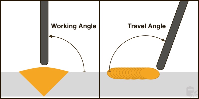
The work angle, which is the relationship between the joint and the torch (or rod).
Ideally, you’ll hold your torch perpendicular, or 90 degrees, to the joint. The big exception to the rule is T-joints, where the work angle varies between 30 to 50 degrees.
Travel Angle
The travel angle is the relationship between the torch and the line of travel. To see the joint and puddle, the welder may tip the rod up to 10 degrees in the direction of travel or sometimes against travel direction.
As you can see in the first diagram, the angle of the torch to the workpiece (left) is 90 degrees, allowing maximum heat and current focused down into the open groove butt joint. (Think of this as the front view of the work plates.)
In the diagram on the right, the travel angle shows a 5-10 degree tilt along the joint. This gives the welder a better view of what’s going on in the puddle.
When you drag your torch or electrode, the tilt is directed towards the puddle, which helps with penetration and achieving a thick bead. When you push, the tilt is away from the puddle, limiting penetration and heat going into the base metal.
Manipulation
This refers to the movement of the welder’s hand as they guide the electrode along the joint.
Achieving tie-in at the toes is paramount, but it’s also important to control penetration and heat.
As described in the types of beads article, a weave, whip, drag or push motion are all examples of manipulation.
Speed
If you move too fast, the size of the weld will be small and achieve insufficient penetration.
Move too slow, and you’ll end up with a fat weld bead and likely too much heat going into your work plates.
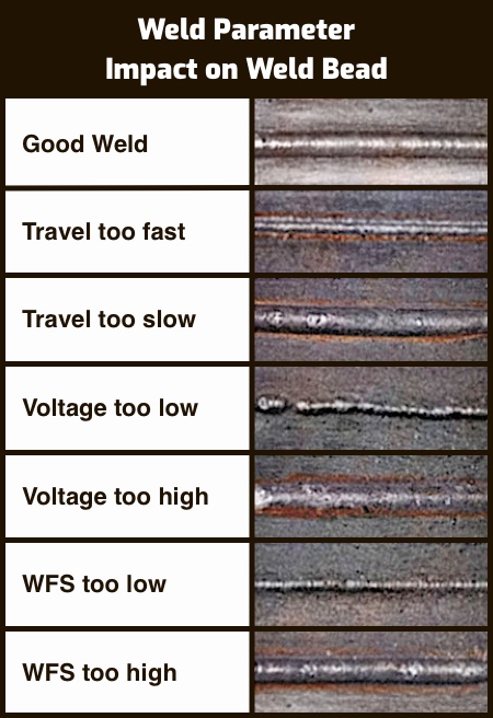
The following chart shows how some CLAMS variables impact a weld bead:

In the last two examples, “WFS” stands for wire feed speed, which is how MIG and flux-cored welding machines regulate current.
Notice that when the voltage is too high, the bead is wide and flat. Also, when the rate of voltage is too low, the weld bead sits on top of the base metal rather than penetrating into it. So voltage determines the overall profile, or geometry, of the weld.
In stick welding, the welder sets the voltage directly but not the current, so the machines are called Constant Current (CC).
In MIG/flux-cored, the machines provide Constant Voltage (CV), so the welder usually only sets the current.
Some stick machines also have a setting known as Dig. This setting allows you to increase the current above the set output amperage if your arc starts to fizzle out.
Although the photos above don’t show it, too long of an arc can cause porosity (air bubbles) inside the weld, spatter on the base metal, and undercutting at the toes of the joint. See the Weld Defects article for more on this subject.
Other Variables to Consider
In addition to CLAMS, there are a few other variables to think about when planning a weld operation:
Joint Design and Fit-Up
How you prepare your work plates (or stationary structure) for welding may contribute more to the outcome of the operation than anything else.
Your joints, beveled edges, ground root faces, and surfaces should fit together in a smooth and uniform manner before you start the weld. There shouldn’t be any burrs, gaps, or evenness.
As a student, it’s easy to assume that once the metal heats up, everything falls together naturally, and all the little rough spots will disappear like magic.
In fact, you can make things worse if you don’t take the time to do your fit-up correctly.
Needless to say, the angle of your beveled sides should be appropriate for the thickness of the metal and the welding process being used. (In MIG welding, steeper angles are possible than in stick welding.)
You should also tack your plates and use clamps as needed to prevent the joint from closing up in advance of the weld or other distortion caused by heat.
Cleaning your weld edges in advance is also important. While some stick electrodes are designed to penetrate through rust and mill scale, those impurities can still cause problems. And while low-carbon steel is much easier to work with than other metals, you should still adopt the habit of cleaning or grinding the areas you plan to weld.
Size
The thickness of the base metal should factor into the decision about which diameter electrode, rod, wire, or torch tip you use to make the weld, as well as your voltage, wire speed, and/or current settings.
There are plenty of other size factors to consider, but metal thickness usually comes first.
Heat Dispersal
Different metals disperse heat differently. The mass of your workpieces also has an effect, with tinier workpieces heating much faster than large, heavy pieces.
Low-carbon steel can be very forgiving when overheated, but other metals may lose tensile strength or other qualities if you don’t monitor the heat going in and out of the plates or pipe.
As you learn more about the chemical and mechanical properties of different metals and alloys, you may decide to include a pre or post-heat treatment or your workpieces as part of the welding operation.
Quenching plates after welding (to cool them down) is a practice that’s generally frowned upon after the first semester of welding school. That’s because the quench has a sort of traumatizing effect on the metal and can make it brittle.
A metallurgy class teaches welders the many forms of heat treatment and their advantages – like hardening, tempering, and annealing.
