Flux Core Welding (FCAW)

Affiliate Disclaimer: This post may contain links that will earn us a commission at no cost to you. This helps keep Weldguru a free resource for our readers.


Flux Core Arc Welding (FCAW) uses a tubular wire that is filled with a flux.

The arc is initiated between the continuous wire electrode and the workpiece.

The flux, which is contained within the core of the tubular electrode, melts during welding and shields the weld pool from the atmosphere. Direct current, electrode positive (DCEP) is commonly employed as in the FCAW process.

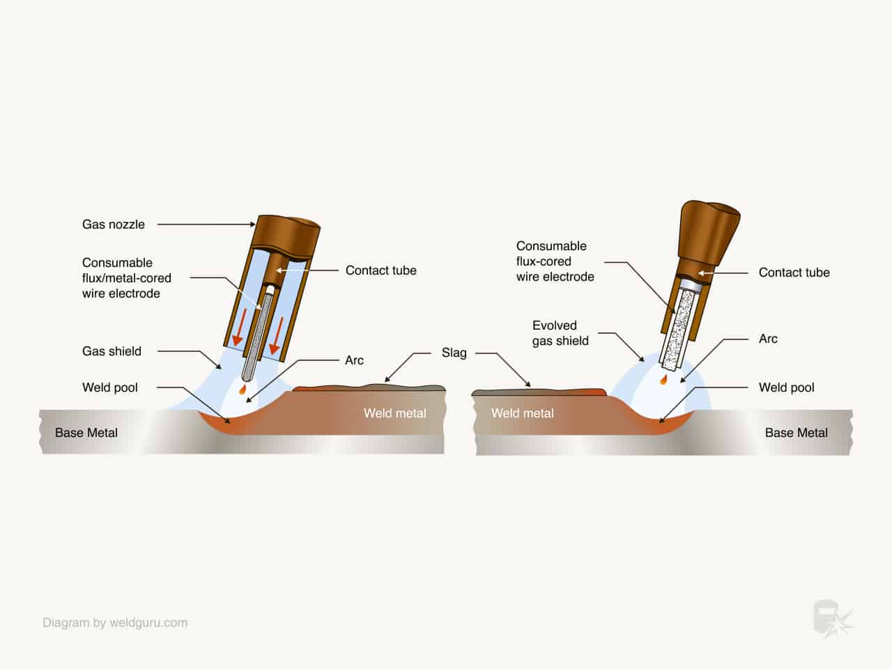
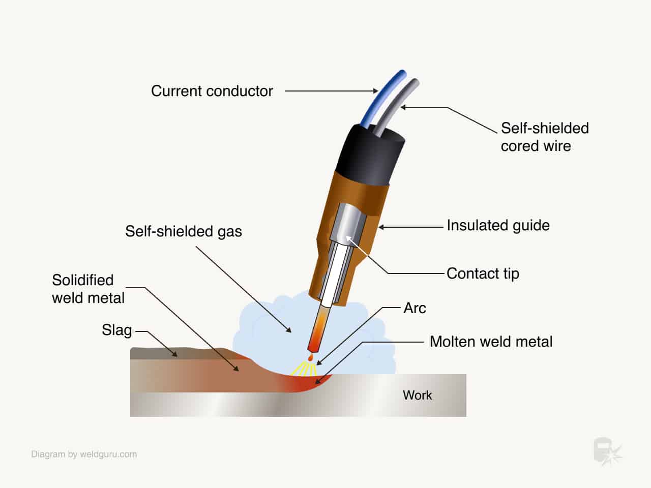
There are two basic process variants; self shielded FCAW (without shielding gas) and gas shielded FCAW (with shielding gas). The difference in the two is due to different fluxing agents in the consumables, which provide different benefits to the user. Usually, self-shielded FCAW is used in outdoor conditions where wind would blow away a shielding gas.

The fluxing agents in self shielded FCAW are designed to not only deoxidize the weld pool but also to allow for shielding of the weld pool and metal droplets from the atmosphere.

The flux in gas-shielded FCAW provides for deoxidation of the weld pool and, to a smaller degree than in self-shielded FCAW, provides secondary shielding from the atmosphere. The flux is designed to support the weld pool for out-of-position welds. This variation of the process is used for increasing the productivity of out-of-position welds and for deeper penetration.

Video: Flux Cored Self Shielded Welding Basics

Flux Core Welding Process

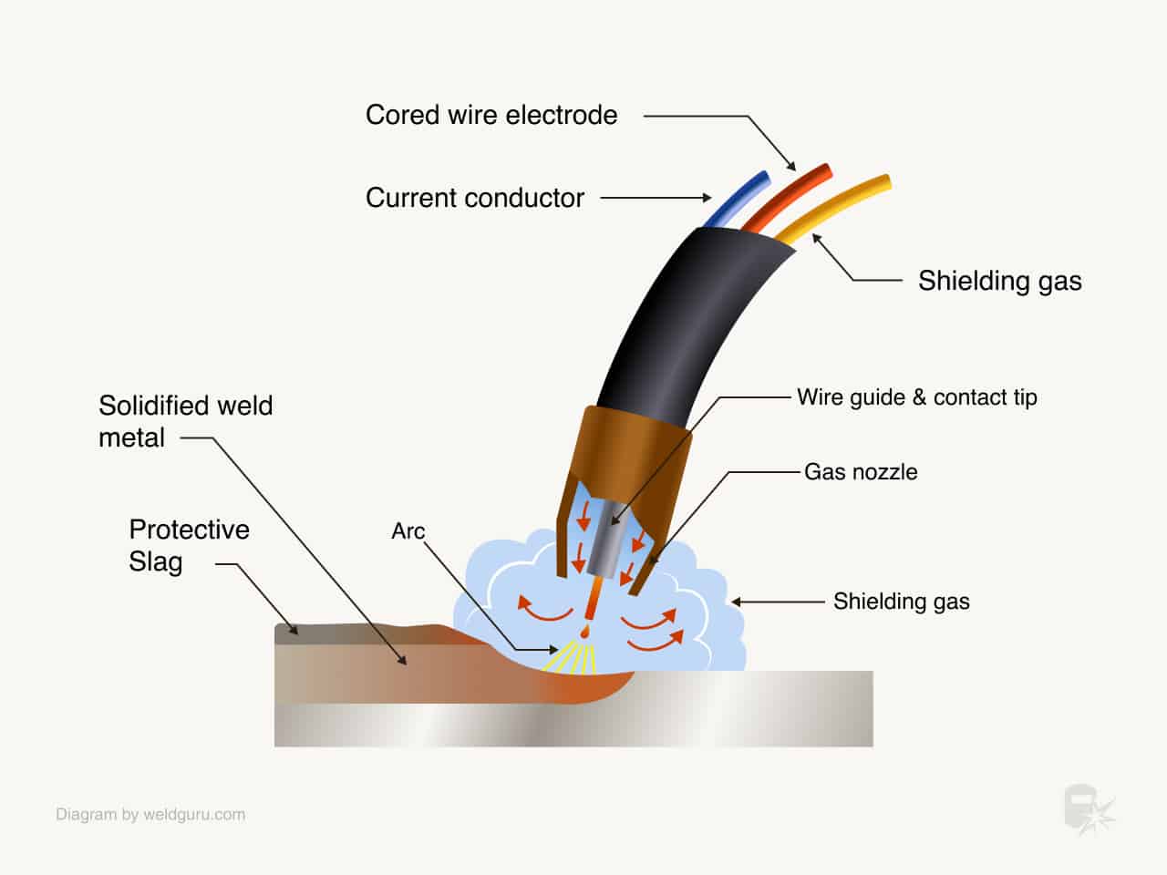
Flux core welding or tubular electrode welding has evolved from the MIG welding process to improve arc action, metal transfer, weld metal properties, and weld appearance. It is an arc welding process in which the heat for welding is provided by an arc between a continuously fed tubular electrode wire and the workpiece.

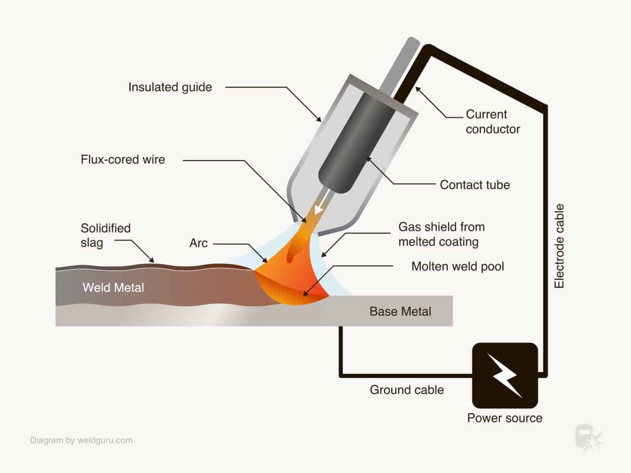
Shielding is obtained by a flux contained within the tubular electrode wire or by the flux and an externally supplied shielding gas. A diagram of the process is shown in figure 10-55 below.

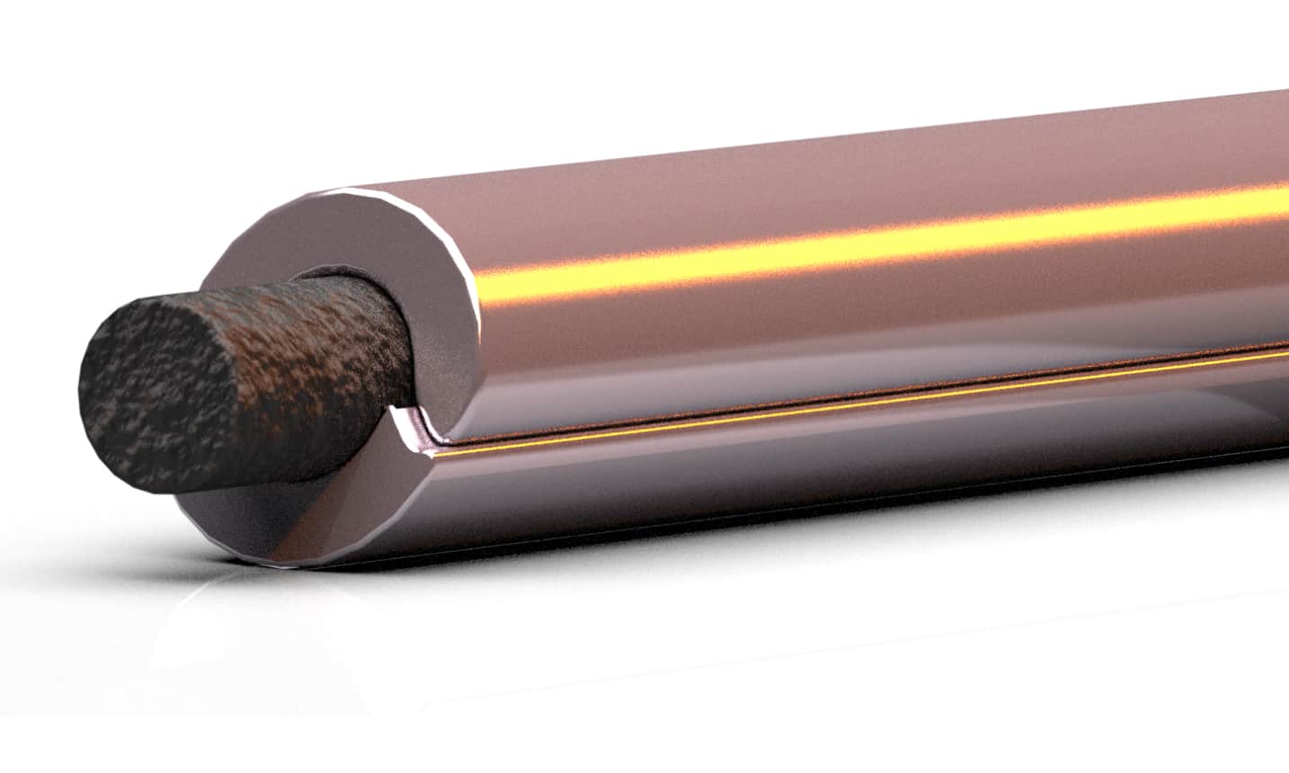
The flux-cored welding wire, or electrode, is a hollow tube filled with a mixture of deoxidizers, fluxing agents, metal powders, and ferro-alloys. The closure seam, which appears as a fine line, is the only visible difference between flux-cored wires and solid cold-drawn wire.

Flux-cored electrode welding can be done in two ways:

  1. Carbon dioxide gas can be used with the flux to provide additional shielding.
  2. The flux core alone can provide all the shielding gas and slagging materials.

The carbon dioxide gas shield produces a deeply penetrating arc and usually provides better weld than is possible without an external gas shield. Although flux-cored arc welding may be applied semiautomatically, by machine, or automatically, the process is usually applied semiautomatically.

In semiautomatic welding, the wire feeder feeds the electrode wire and the power source maintains the arc length. The welder manipulates the welding gun and adjusts the welding parameters.

Flux-cored arc welding is also used in machine welding where, in addition to feeding the wire and maintaining the arc length, the machinery also provides the joint travel.

The welding operator continuously monitors the welding and makes adjustments in the welding parameters. Automatic welding is used in high production applications.

flux cored welding process diagram
Flux Cored Welding Process Diagram

Also read: What is Arc Welding?

Welding Tips

  • Do not use smooth wire drive rolls, use the knurled drive rolls
  • Change polarity to electrode negative (check with the manufacturer, MIG is usually electrode positive)
  • Use adequate ventilation
  • 1/2″ to 3/4″ wire stick out
  • Drag the gun (backhand weld)
  • For flat weld, weld at 90 degrees and 10 degrees back. T Joint at 45 degrees.  Lap joint at 60 degrees to 70 degrees with one straight weld.
  • For horizontal angle gun upwards at around 10 degrees, turn welding parameters on the machine down about 10 to 15%.
  • For vertical weld (can use up or down, vertical down is better for thinner metals, us vertical up for 1/4″ and above,  also turn parameters down 10 to 15% on the machine.
  • For overhead try and maintain fast travel speed and also reduce welding parameters by 10% to 15% (as compared to flat or horizontal weld).
  • Weld side to side to avoid undercut
  • Thoroughly clean off slag after each pass

FCAW vs. GMAW and SMAW

The FCAW flux core process combines the best characteristics of SMAW and GMAW.

It uses a flux to shield the weld pool, although a supplemental shielding gas can be used. A continuous wire electrode provides high deposition rates.

FCAW vs GMAW

Flux-cored arc welding is similar to gas metal arc welding (GMAW or MIG) in many ways. The flux-cored wire used for this process gives it different characteristics. Flux-cored arc welding is widely used for welding ferrous metals and is particularly good for applications in which high deposition rates are needed. At high welding currents, the arc is smooth and more manageable when compared in using large-diameter gas metal arc welding electrodes with carbon dioxide.

The arc and weld pool are clearly visible to the welder. A slag coating is left on the surface of the weld bead, which must be removed. Since the filler metal transfers across the arc, some spatter is created and some smoke produced.

The flux for FCAW consumables can be designed to support larger weld pools out of position and provide higher penetration than a solid MIG wire (GMAW). Larger welds can be made in a single pass with larger diameter electrodes whereas GMAW and SMAW would need multiple passes for equivalent weld sizes. This improves productivity and reduces the distortion of a weldment.

FCAW vs SMAW

As with SMAW, the slag must be removed between passes on multipass welds. This can slow down the productivity of the application and result in possible slag inclusion discontinuities. For gas-shielded FCAW, porosity can occur due to insufficient gas coverage.

Large amounts of fume are produced by the FCAW process due to the high currents, voltages, and the flux inherent in the process. Increased costs could be incurred through the need for ventilation equipment for proper health and safety.

FCAW is more complex and more expensive than SMAW because it requires a wire feeder and welding gun. The complexity of the equipment also makes the process less portable than SMAW.

Flux Cored Welding Equipment

flux cored welder
Versatile Miller Trailblazer 302 Engine Driven Welder / Generator, Gas, 1- Phase, 30 – 225 AC, 10 – 325 DC Type: (KOHLER). Supports Stick (SMAW), MIG (GMAW, Flux Cored (FCAW), DC TIG (DC GTAW), AC TIG (AC GTAW), Air Carbon Arc (CAC-A) Cutting and Gouging

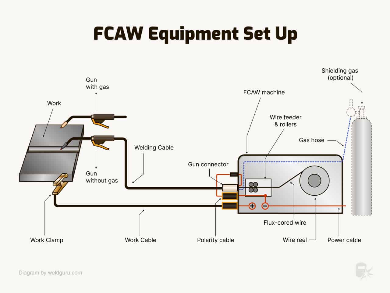
The equipment used for flux core welding is similar to that used for gas metal arc welding.

The basic arc welding equipment consists of:

  • A power source
  • Controls
  • Wire feeder
  • Welding gun
  • Welding cables

A major difference between the gas-shielded and self-shielded electrodes is that the gas-shielded wires also require a gas-shielding system.

This may also have an effect on the type of welding gun used. Fume extractors are often used in this process.

For machines and automatic welding, several items, such as seam followers and motion devices, are added to the basic equipment.

Diagram Of Semiautomatic Welding Equipment
Diagram of Semiautomatic Flux-cored Arc Welding Equipment

Power Source

The power source, or welding machine, provides the electric power of the proper voltage and amperage to maintain a welding arc. Most power sources operate on 230 or 460 volt input power, but machines that operate on 200 or 575 volt input are also available. Power sources may operate on either single phase or three-phase input with a frequency of 50 to 60 hertz.

Most power sources used for flux-cored arc welding have a duty cycle of 100 percent, which indicates they can be used to weld continuously. Some machines used for this process have duty cycles of 60 percent, which means that they can be used to weld 6 of every 10 minutes.

The power sources generally recommended for flux-cored arc welding are direct current constant voltage type. Both rotating (generator) and static (single or three-phase transformer-rectifiers) are used. The same power sources used with gas metal arc welding are used with flux-cored arc welding.

Flux-cored arc welding generally uses higher welding currents than gas metal arc welding, which sometimes requires a larger power source. It is important to use a power source that is capable of producing the maximum current level required for an application.

Direct Current Process

Flux-cored arc welding uses direct current. Direct current can be either reverse or straight polarity. Flux-cored electrode wires are designed to operate on either DCEP or DCEN. The wires designed for use with an external gas shielding system are generally designed for use with DCEP. Some self-shielding flux-cored ties are used with DCEP while others are developed for use with DCEN.

Electrode-positive current gives better penetration into the weld joint. Electrode negative current gives lighter penetration and is used for welding thinner metal or metals where there is poor fit-up. The weld created by DCEN is wider and shallower than the weld produced by DCEP.

The generator welding machines used for the flux core process can be powered by an electric rotor for shop use, or by an internal combustion engine for field applications. The gasoline or diesel engine-driven welding machines have either liquid or air-cooled engines.

Motor-driven generators produce a very stable arc, but are noisier, more expensive, consume more power, and require more maintenance than transformer-rectifier machines.

Wire Feed Motor

A wire feed motor provides power for driving the electrode through the cable and gun to the work. There are several different wire feeding systems available. System selection depends upon the application. Most of the wire feed systems used for flux-cored arc welding are the constant speed type, which is used with constant voltage power sources. With a variable speed wire feeder, a voltage sensing circuit is used to maintain the desired arc length by varying the wire feed speed.

Variations in the arc length increase or decrease the wire feed speed. A wire feeder consists of an electrical rotor connected to a gearbox containing drive rolls. The gear box and wire feed motor shown in figure 10-57 have form feed rolls in the gearbox.

FCAW Wire Feed Assembly

Air and Water Cooled Welding Guns

Both air-cooled and water-cooled guns are used for flux-cored arc welding. Air-cooled flux core guns are cooled primarily by the surrounding air, but a shielding gas, when used, provides additional cooling effects. A water-cooled gun has ducts to permit water to circulate around the contact tube and nozzle.

Water-cooled flux core guns permit more efficient cooling of the gun. Water-cooled guns are recommended for use with welding currents greater than 600 amperes, and are preferred for many applications using 500 amperes. Welding guns are rated at the maximum current capacity for continuous operation.

Air-cooled guns are preferred for most applications of less than 500 amperes, although water-cooled guns may also be used. Air-cooled guns are lighter and easier to manipulate.

Shielding Gases

Shielding gas equipment used for gas-shielded flux-cored wires consists of a gas supply hose, a gas regulator, control valves, and supply hose to the welding gun. (as noted above flux core can be used without shielding gas depending on the application)

The shielding gases are supplied in liquid form when they are in storage tanks with vaporizers, or in a gas form in high-pressure cylinders. An exception to this is carbon dioxide. When put in high-pressure cylinders, it exists in both liquid and gas forms.

The primary purpose of the shielding gas is to protect the arc and weld puddle from contaminating effects of the atmosphere. The nitrogen and oxygen of the atmosphere, if allowed to come in contact with the molten weld metal, cause porosity and brittleness.

In flux-cored arc welding, shielding is accomplished by the decomposition of the electrode core or by a combination of this and surrounding the arc with a shielding gas supplied from an external source. A shielding gas displaces air in the arc area. Welding is accomplished under a blanket of shielding gas. Inert and active gases may both be used for flux-cored arc welding.

Active gases such as carbon dioxide, argon-oxygen mixture, and argon-carbon dioxide mixtures are used for almost all applications. Carbon dioxide is the most common. The choice of the proper shielding gas for a specific application is based on the type of metal to be welded, arc characteristics and metal transfer, availability, cost of the gas, mechanical property requirements, and penetration and weld bead shape. The various shielding gases are summarized below.

Carbon dioxide

Carbon dioxide is manufactured from fuel gases that are given off by the burning of natural gas, fuel oil, or coke. It is also obtained as a by-product of calcining operation in lime kilns, from the manufacturing of ammonia and from the fermentation of alcohol, which is almost 100 percent pure.

Carbon dioxide is made available to the user in either cylinder or bulk containers. The cylinder is more common. With the bulk system, carbon dioxide is usually drawn off as a liquid and heated to the gas state before going to the welding torch. The bulk system is normally only used when supplying a large number of welding stations.

In the cylinder, the carbon dioxide is in both a liquid and a vapor form with the liquid carbon dioxide occupying approximately two-thirds of the space in the cylinder. By weight, this is approximately 90 percent of the content of the cylinder. Above the liquid, it exists as a vapor gas. As carbon dioxide is drawn from the cylinder, it is replaced with carbon dioxide that vaporizes from the liquid in the cylinder and therefore the overall pressure will be indicated by the pressure gauge.

When the pressure in the cylinder has dropped to 200 psi (1379 kPa), the cylinder should be replaced with a new cylinder. A positive pressure should always be left in the cylinder in order to prevent moisture and other contaminants from backing up into the cylinder. The normal discharge rate of the CO2 cylinder is about 10 to 50 cu ft per hr (4.7 to 24 liters per min). However, a maximum discharge rate of 25 cu ft per hr (12 liters per min is recommended when welding using a single cylinder.

As the vapor pressure drops from the cylinder pressure to discharge pressure through the CO2 regulator, it absorbs a great deal of heat. If flow rates are set too high, this absorption of heat can lead to freezing of the regulator and flowmeter which interrupts the shielding gas flow. When flow rate higher than 25 cu ft per hr (12 liters per min) is required, normal practice is to manifold two CO2 cylinders in parallel or to place a heater between the cylinder and gas regulator, pressure regulator, and flowmeter.

Excessive flow rates can also result in drawing liquid from the cylinder. Carbon dioxide is the most widely used shielding gas for flux-cored arc welding. Most active gases cannot be used for shielding, but carbon dioxide provides several advantages for use in welding steel. These are deep penetration and low cost. Carbon dioxide promotes a globular transfer. The carbon dioxide shielding gas breaks down into components such as carbon monoxide and oxygen. Because carbon dioxide is an oxidizing gas, deoxidizing elements are added to the core of the electrode wire to remove oxygen.The oxides formed by the deoxidizing elements float to the surface of the weld and become part of the slag covering. Some of the carbon dioxide gas will break down to carbon and oxygen. If the carbon content of the weld pool is below about 0.05 percent, carbon dioxide shielding will tend to increase the carbon content of the weld metal. Carbon, which can reduce the corrosion resistance of some stainless steels, is a problem for critical corrosion application. Extra carbon can also reduce the toughness and ductility of some low alloy steels. If the carbon content in the weld metal is greater than about 0.10 percent, carbon dioxide shielding will tend to reduce the carbon content. This loss of carbon can be attributed to the formation of carbon monoxide, which can be trapped in the weld as porosity deoxidizing elements in the flux core reducing the effects of carbon monoxide formation.Argon-carbon dioxide mixtures.

Argon and carbon dioxide

are sometimes mixed for use with flux-cored arc welding. A high percentage of argon gas in the mixture tends to promote a higher deposition efficiency due to the creation of less spatter. The most commonly used gas mixture in flux-cored arc welding is a 75 percent argon-25 percent carbon dioxide mixture. The gas mixture produces a fine globular metal transfer that approaches a spray. It also reduces the amount of oxidation that occurs, compared to pure carbon dioxide. The weld deposited in an argon-carbon dioxide shield generally has higher tensile and yield strengths. Argon-carbon dioxide mixtures are often used for out-of-position welding, achieving better arc characteristics. These mixtures are often used on low alloy steels and stainless steels. Electrodes that are designed for use with CO2 may cause an excessive buildup of manganese, silicon, and other deoxidizing elements if they are used with shielding gas mixtures containing a high percentage of argon. This will have an effect on the mechanical properties of the weld.

Argon-oxygen mixtures

Argon-oxygen mixtures containing 1 or 2 percent oxygen are used for some applications. Argon-oxygen mixtures tend to promote a spray transfer which reduces the amount of spatter produced. A major application of these mixtures is the welding of stainless steel where carbon dioxide can cause corrosion problems.

Electrodes

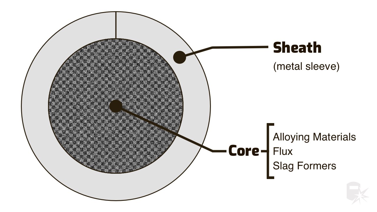
Cross Section of Flux Core Wire
Cross Section of Flux Core Wire – figure 10-58

The electrodes used for flux-cored arc welding provide the filler metal to the weld puddle and shielding for the arc.

Shielding is required for sane electrode types. The purpose of the shielding gas is to provide protection from the atmosphere to the arc and molten weld puddle.

The chemical composition of the electrode wire and flux core, in combination with the shielding gas, will determine the weld metal composition and mechanical properties of the weld.

The electrodes for flux-cored arc welding consist of a metal shield surrounding a core of fluxing and/or alloying compounds as shown in figure 10-58.

The cores of carbon steel and low alloy electrodes contain primarily fluxing compounds.

Related: What is Flux in Welding?

Some of the low alloy steel electrode cores contain high amounts of alloying compounds with a low flux content. Most low alloy steel electrodes require gas shielding.

The sheath comprises approximately 75 to 90 percent of the weight of the electrode. Self-shielded electrodes contain more fluxing compounds than gas-shielded electrodes.

The compounds contained in the electrode perform basically the same functions as the coating of a covered electrode used in shielded metal arc welding.

These functions are:

  1. To form a slag coating that floats on the surface of the weld metal and protects it during solidification.
  2. To provide deoxidizers and scavengers which help purify and produce solid weld-metal.
  3. To provide arc stabilizers that produce a smooth welding arc and keep spatter to a minimum.
  4. To add alloying elements to the weld metal which will increase the strength and improve other properties in the weld metal.
  5. To provide shielding gas. Gas-shielded wires require an external supply of shielding gas to supplement that produced by the core of the electrode.

Classification System for Tubular Wire Electrodes

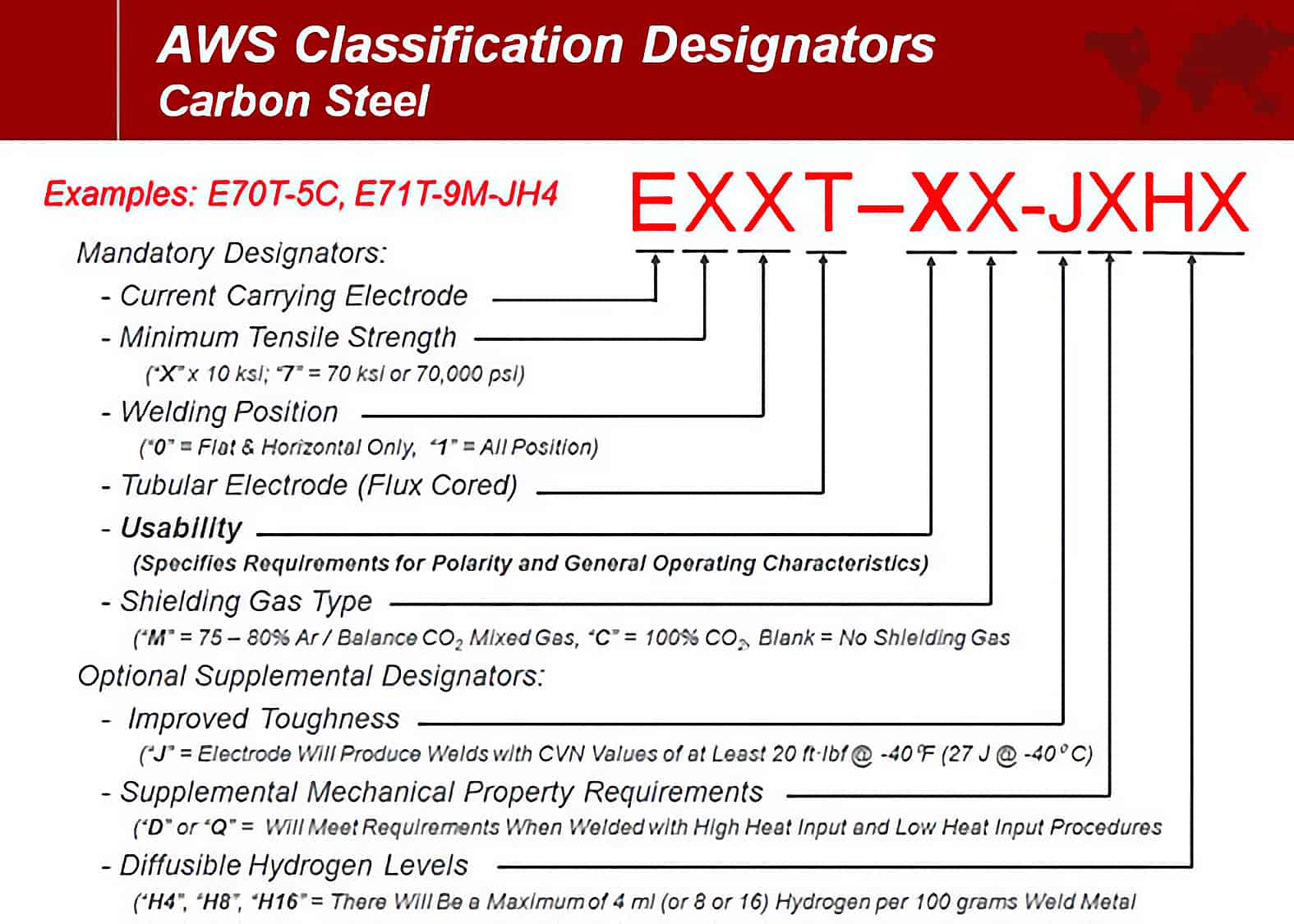
The classification system used for tubular wire electrodes used as part of flux core welding was devised by the American Welding Society. Carbon and low alloy steels are classified based on the following items:

  1. Mechanical properties of the weld metal.
  2. Welding position.
  3. Chemical composition of the weld metal.
  4. Type of welding current.
  5. Whether or not a CO2 shielding gas is used.

An example of a carbon steel electrode classification is E70T-4 where:

  1. The “E” indicates an electrode.
  2. The second digit or “7” indicates the minimum tensile strength in units of 10,000 psi (69 MPa).
  3. The third digit or “0” indicates the welding positions. A “0” indicates flat and horizontal positions and a “1” indicates all positions. 4. The “T” stands for a tubular or flux cored wire classification. 5. The suffix “4” gives the performance and usability capabilities as shown in table 10-13.  When a “G” classification is used, no specific performance and usability requirements are indicated. This classification is intended for electrodes not covered by another classification. The chemical composition requirements of the deposited weld metal for carbon steel electrodes are shown in table 10-14.Single pass electrodes do not have chemical composition requirements because checking the chemistry of undiluted weld metal does not give the true results of normal single pass weld chemistry.

Carbon Flux Steel Electrodes

Mechanical Property Requirements of Carbon Steel Flux Cored Electrodes
Mechanical Property Requirements of Carbon Steel Flux-Cored Electrodes – Table 10-12
Performance and Usability Characteristics of Carbon Steel Flux Cored Electrodes
Performance and Usability Characteristics of Carbon Steel Flux Cored Electrodes – Table 10-13
Chemical Composition Requirements of Carbon Steel Flux Cored Electrodes
Chemical Composition Requirements of Carbon Steel Flux Cored Electrodes – Table 10-14

The classification of low alloy steel electrodes used in flux core welding is similar to the classification of carbon steel electrodes. An example of a low alloy steel classification is E81T1-NI2 where:

  1. The “E” indicates electrode.
  2. The second digit or “8” indicates the minimum tensile in strength in units of 10,000 psi (69 MPa). In this case it is 80,000 psi (552 MPa). The mechanical property requirements for low alloy steel electrodes are shown in table 10-15. Impact strength requirements are shown in table 10-16.
  3. The third digit or “1” indicates the welding position capabilities of the electrode. A “1” indicates all positions and an “0” flat and horizontal position only.
  4. The “T” indicates a tubular or flux-cored electrode used in flux cored arc welding.
  5. The fifth digit or “1” describes the usability and performance characteristics of the electrode. These digits are the same as used in carbon steel electrode classification but only EXXT1-X, EXXT4-X, EXXT5-X and EXXT8-X are used with low alloy steel flux-cored electrode classifications.
  6. 6. The suffix or “Ni2” tells the chemical composition of the deposited weld metal as shown in table 10-17 below.
Mechanical Property Requirements of Low Alloy Flux Cored Electrodes
Mechanical Property Requirements of Low Alloy Flux-Cored Electrodes – Table 10-15
Impact Requirements For Low Alloy Flux Cored Electrodes
Impact Requirements For Low Alloy Flux Cored Electrodes – Table 10-16
Chemical Composition Requirements for Low Alloy Flux Cored Electrodes
Chemical Composition Requirements for Low Alloy Flux-Cored Electrodes – Table 10-17 (chemical composition percent (a)

a. Single values are maximum unless otherwise noted
b. For self-shielded electrodes only
c. In order to meet the alloy requirements of the G group, the weld deposit have the minimum, as specific in the table of only one of the elements
d. The E80TI-W classification also contains .30 – .75 percent copper

Stainless Steel Electrodes

The classification system for stainless steel electrodes used in flux core welding is based on the chemical composition of the weld metal and the type of shielding to be employed during welding. An example of a stainless steel electrode classification is E308T-1 where:

  1. The “E” indicates the electrode.
  2. The digits between the “E” and the “T” indicate the chemical composition of the weld as shown in table 10-18 below.
  3. The “T” designates a tubular or flux-cored electrode wire.
  4. The suffix of “1” indicates the type of shielding to be used as shown in table 10-19 below.
Weld Metal Chemical Composition Requirements for Stainless Steel Electrodes
Weld Metal Chemical Composition Requirements for Stainless Steel Electrodes – Table 10-18
shielding table
Shielding – Table 10-19

Also see: 0.030 vs 0.035 Flux Core Wire

Welding Cables

The welding cables and connectors are used to connect the power source to the welding gun and to the work. These cables are normally made of copper. The cable consists of hundreds of wires that are enclosed in an insulated casing of natural or synthetic rubber. The cable that connects the power source to the welding gun is called the electrode lead.

In semiautomatic welding, this cable is often part of the cable assembly, which also includes the shielding gas hose and the conduit that the electrode wire is fed through. For machine or automatic welding, the electrode lead is normally separate. The cable that connects the work to the power source is called the work lead. The work leads are usually connected to the work by pinchers, clamps, or a bolt.

The size of the welding cables used depends on the output capacity of the flux core welding machine, the duty cycle of the machine, and the distance between the welding machine and the work. Cable sizes range from the smallest AWG No 8 to AWG No 4/0 with amperage ratings of 75 amperes on up.

Table 10-20 shows recommended cable sizes for use with different welding currents and cable lengths. A cable that is too small may become too hot during welding.

Recommended Cable Sizes for Different Welding Currents
Recommended Cable Sizes for Different Welding Currents – Table 10-20

Pros and Cons of FCAW

Advantages: Reduced Cost and Higher Deposition

Summary:

  • High deposition rates
  • Deeper penetration than  SMAW
  • High-quality
  • Less pre-cleaning than GMAW
  • Slag covering helps with larger out-of-position welds Self-shielded FCAW is draft tolerant

The major advantages of flux core welding are reduced cost and higher deposition rates than either SMAW or solid wire GMAW.

The cost is less for flux-cored electrodes because the alloying agents are in the flux, not in the steel filler wire as they are with solid electrodes.

Flux-cored welding is ideal where bead appearance is important and no machining of the weld is required. Flux-cored welding without carbon dioxide shielding can be used for most mild steel construction applications.

The resulting welds have higher strength but less ductility than those for which carbon dioxide shielding is used. There is less porosity and greater penetration of the weld with carbon dioxide shielding. The flux-cored process has increased tolerances for scale and dirt.

There is less weld spatter for flux core welding than with solid-wire MIG welding. It has a high deposition rate, and faster travel speeds are often used. Using small diameter electrode wires, welding can be done in all positions. Some flux-cored wires do not need an external supply of shielding gas, which simplifies the equipment.

The electrode wire is fed continuously so there is very little time spent on changing electrodes. A higher percentage of filler metal is deposited when compared to shield metal arc welding. Finally, better penetration is obtained than from shielded metal arc welding.

Disadvantages: Sensitivity to Welding Conditions

Flux core welding disadvantages summary:

  • Slag must be removed
  • More smoke and fumes than GMAW and SAW
  • Spatter
  • FCAW wire is more expensive
  • Equipment is more expensive and complex than for SMAW

Most low-alloy or mild-steel electrodes of the flux-cored type are more sensitive to changes in welding conditions than are SMAW electrodes.

This sensitivity, called voltage tolerance, can be decreased if a shielding gas is used, or if the slag-forming components of the core material are increased.

A constant-potential power source and constant-speed electrode feeder are needed to maintain a constant arc voltage.

FCAW Troubleshooting

When troubleshooting flux core welds, be sure to check the manufacturers directions (found inside the equipment panel) for the following (described in detail below):

  • Wire Feed Speed
  • Travel Speed
  • Contact Tip to Work Distance
  • Feeder Polarity
  • Work angle and travel angle
  • Too Low Of a Wire Feed Feed and Current (higher speeds = higher current, lower speeds, lower current: If the speed is too low, you will not get complete coverage, a narrow beed and alot of spatter.

FCAW Troubleshooting Video

FCAW Weld Created At Low Wire Speed

Low wire speed for FCAW weld resulted in hard to remove slag and a lot of spatter. If wire speed is too high the wire will keep stubbing. To fix turn voltage up or wire speed down.

FCAW Weld Created At High Wire Speed

Travel speed too slow: result is a convex wide weld. The slag doesn’t cover properly.

FCAW Weld With Low Travel Speed

Travel speed faster than what is recommended: results in a narrow convex weld bead.  Compare to too flow travel speed above vs. outrunning puddle below.

FCAW Weld With Fast Travel Speed

Contact tip to work distance: Check correct distance for your wire. Too short distance results in inadequate coverage due to the improper preheating of the flux inside the wire.  The slag does not cover the entire weld making the slag look dark down the center of the weld.

If the distance is too far, there will be some stubbing of the weld.  The wire looks like it is hunting for the weld, makes the feeding inconsistent causing ripples in the weld.

FCAW Contact Tip to Work Distance Troubleshooting
Contact tip to work distance is too far (top) and too short (bottom). Check manufacturers directions for correct distance (usually 1/2″ to 5/8″)

Polarity: each wire has recommended polarity. Sometimes DC negative is used when DC positive is needed.  Causes spatter and a small weld.

FCAW Polarity Troubleshooting
Spatter due to wrong polarity. Make Sure that You are Using the Correct Polarity when Flux Core Welding. Do not use DC Positive if DC Negative is Required. Check Diagram of Machine Setup. Check how Feeder is Connected to Welding Equipment.
FCAW Polarity Feeder Polarity
Make Sure the Feeder is Connected to the Correct Poles. Review Diagram inside of Equipment Panel

Electrode Angles: For flux core, remember that there is slag you drag. So make sure that you drag the electrode to allow the slag to form behind the weld. It is lighter than the molten puddle and it will float to the top. If you push it you chance getting slag inclusions in the weld.

Check the work and travel angle: If welding on a flat surface, the angle could be 90 degrees. For a lap joint or T joint you want to be 45 degrees to the joint and a 5 to 10 degrees for the drag.


Want to learn more about welding for free?

Sign up and join 10,000+ other learners and get free welding articles and tips sent straight to your inbox.

What's Your Favourite Arc Welding Process? 


About Jeff Grill

Jeff Grill hails from Long Island, a 118 mile stretch of land that starts just off the coast of Manhattan and stretches deep into the Atlantic ocean. He has always been interested in welding from an early age and has the cuts and bruises to prove it as he set out to work with a variety of metals.


1 thought on “Flux Core Welding (FCAW)”

Leave a Comment

This site is protected by reCAPTCHA and the Google Privacy Policy and Terms of Service apply.