Fillet welds are some of the most common welds you’ll encounter as a welder.
The AWS defines a fillet weld as: “A weld of approximately triangular cross-section joining two surfaces approximately at right angles to each other in a lap joint, T-joint, or corner joint.”
You must understand fillet weld symbols because factors like size, shape, length, spacing, and contour are essential to a successful weld.
Basics of Fillet Welds
As the AWS definition states, a fillet weld joins two plates that are perpendicular to each other. If you cut the weld in half and look at it from a side view, you’ll see it’s triangular.
You’ll see these welds used throughout the industry anywhere you join two pieces of steel in a roughly ninety-degree angle.
You may see fillet welds used for plates at other angles, as well, but the structure and interpretation of the symbol remain the same.
© weldguru.com – Image usage rights
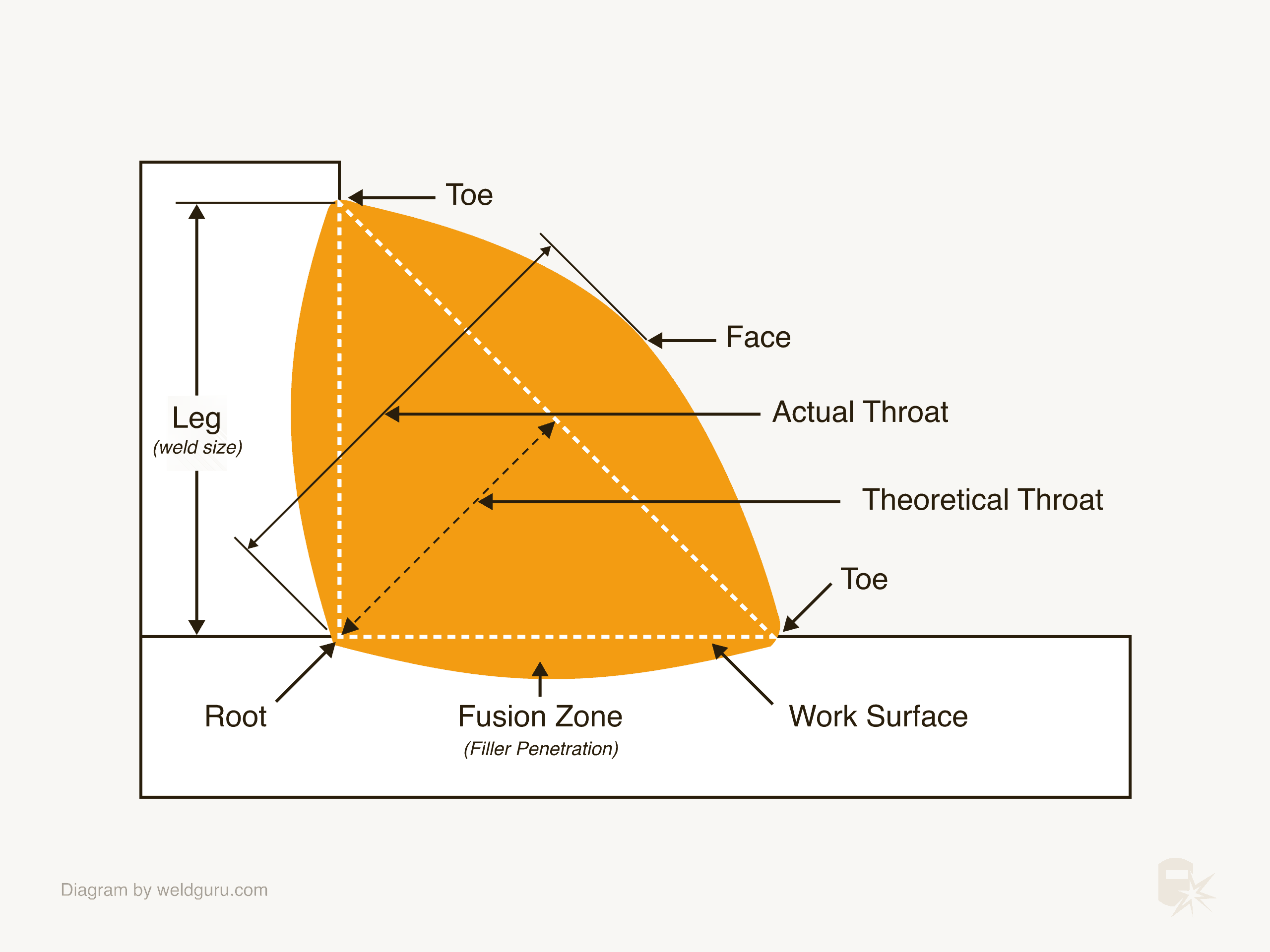
To better understand what the fillet weld symbol is asking you to do, you need a good understanding of the parts of a fillet weld and how to measure them.
- Root – The weld joint’s root is where the two plates meet. The root of the weld is the point where the weld metal extends past the root of the joint.
- Leg – The leg length is the standard measurement of the size of a fillet weld. It’s the distance from the flat surface of the plate to the toe of the weld. The best way to measure the leg length of a fillet weld is to use a fillet gauge.
- Face – The face of a fillet weld is the visible surface of the fillet weld. The face can be convex, concave, or flat.
- Toe – The toe of a weld is the edge of the weld. If you get undercut, it will be in the toe of the weld.
- Throat – There are two types of throat in a fillet weld. The theoretical or effective throat is a measurement from an imaginary line connecting the toes down to the root of the weld joint. The actual throat is the distance from the weld joint’s root to the weld’s face.
It’s important to understand these terms to know how to produce what the various parts of a fillet weld symbol ask of you.
The Anatomy of a Fillet Weld Symbol
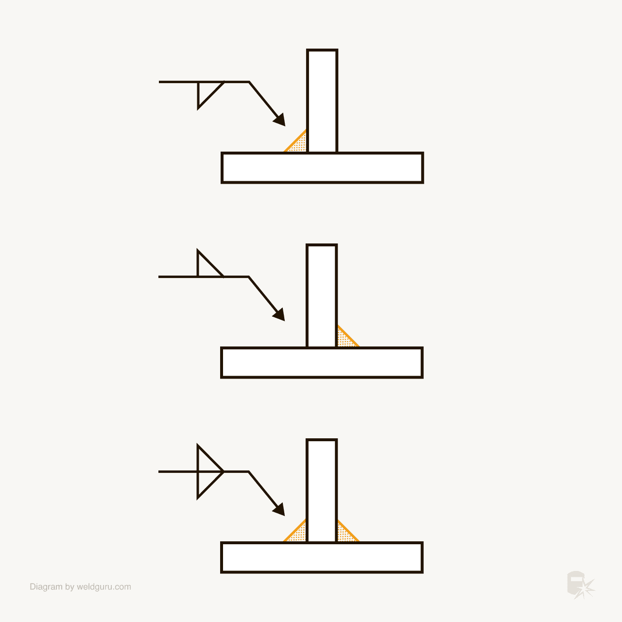
The fillet weld symbol is like other weld symbols in that its position on the reference line indicates where it’s to be in relation to the weld joint.
© weldguru.com – Image usage rights
The lower side of the reference line is the arrow side. This means that when the weld symbol is on this side, the weld is to be on the side of the weld joint that the arrow is pointing to.
The upper side of the reference line is the other side. When a weld symbol is on this side, the weld is to be on the opposite side of the weld joint that the arrow is pointing to.
If a fillet weld symbol is on both sides of the reference line, the weld will be on both sides of the weld joint.
Dimensions on a Fillet Weld Symbol
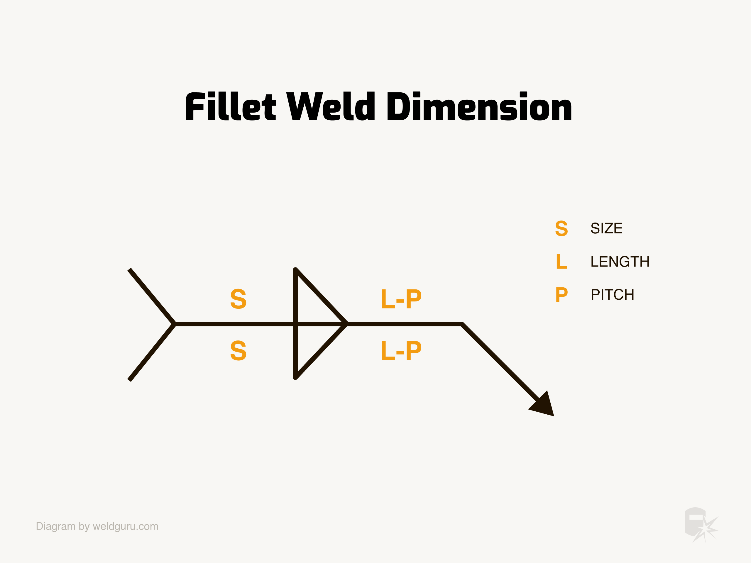
The fillet weld symbol can be made up of three dimensions as shown in the image below:
© weldguru.com – Image usage rights
- Size – Defines how high the weld should protrude from the joint.
- Length – Defines how long the weld should be.
- Pitch – If an intermittent weld is required, then the pitch is the gap between each weld. This is measured from the center of each weld, not the end.
All sizes are in imperial inches.
Let’s take a look at these more closely.
Indicating the Fillet Weld Size
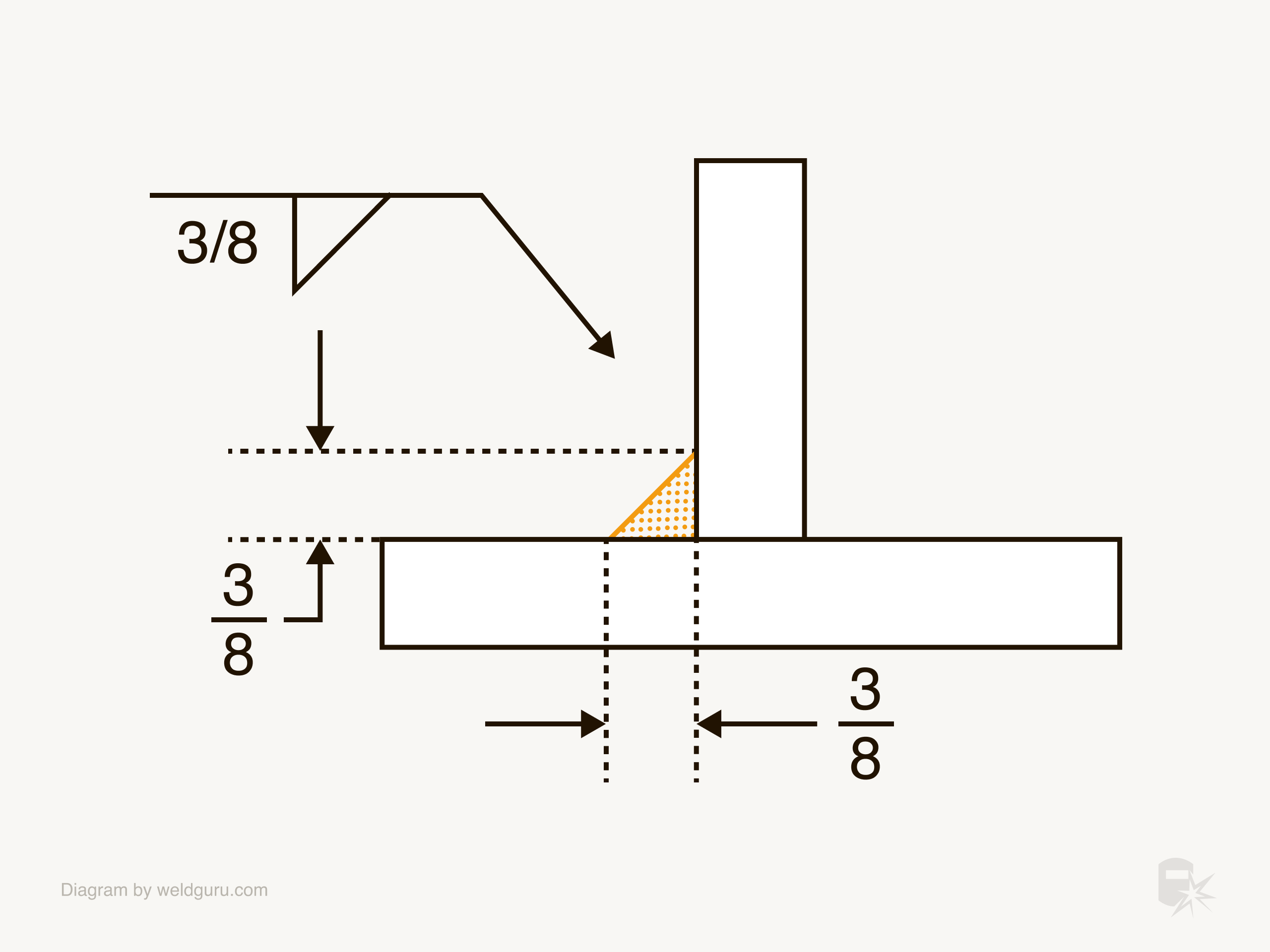
When a specific size of a fillet weld is required, you’ll see a dimension to the left of the weld symbol. This measurement is the minimum leg length required for the fillet.
There are a few unique scenarios regarding fillet weld size, which I’ll address here:
© weldguru.com – Image usage rights
In the above example, the weld symbol calls for a ⅜” fillet weld on the arrow side of the joint. This means that each leg of the weld must be ⅜” long, and the weld is to be on the side of the joint the arrow points to.
© weldguru.com – Image usage rights
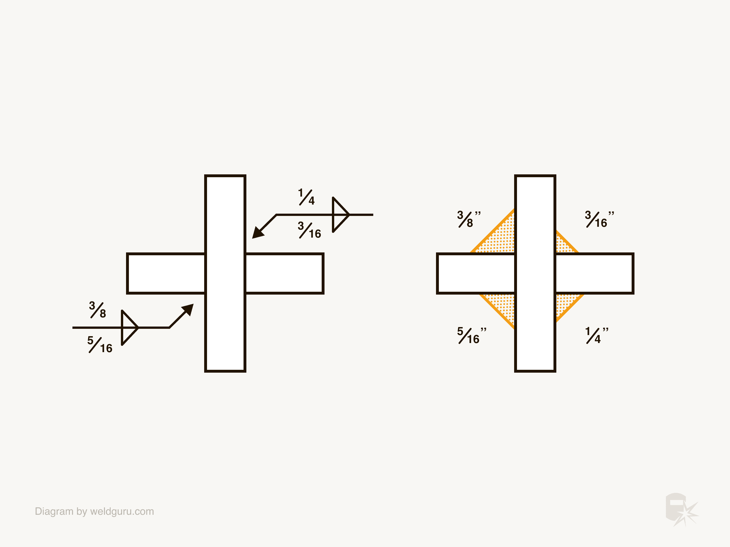
If the welds on either side of the weld joint need to be different sizes, each weld symbol will have its own dimension listed.
In the above example, the arrow side on the left weld symbol requires a 5/16″ weld, and on the right a 3/16″ weld. The other side on the left welding symbol requires a 3/8″ weld and 1/4″ on the right.
© weldguru.com – Image usage rights
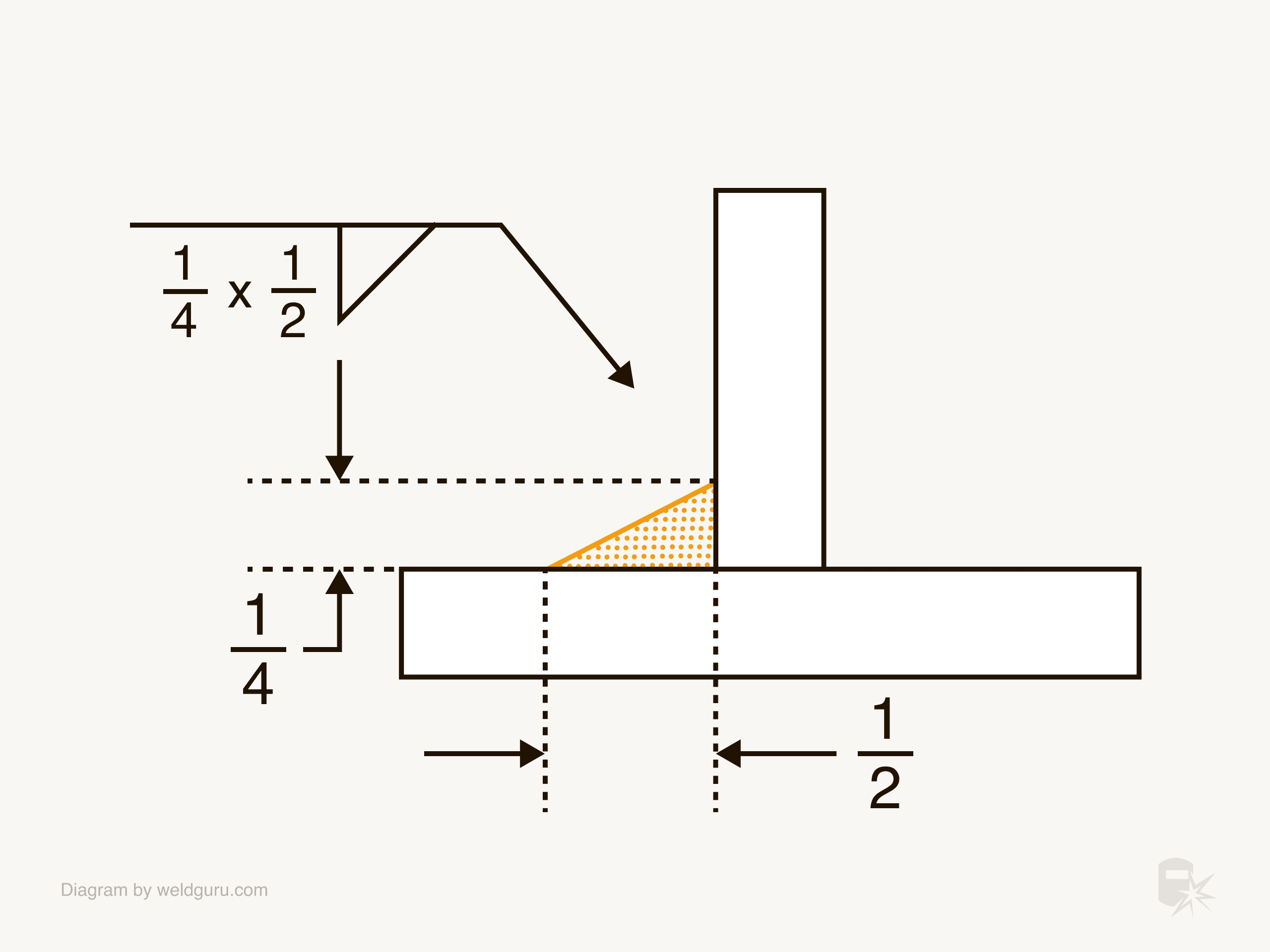
There are instances where the leg lengths of the weld must be different. In this case, you’ll see two dimensions to the left of the weld symbol.
In the example above, the weld is to be ¼” by ½” to the arrow side. In this example, the ½” leg is the lower leg, and the ¼” leg is the upper leg. You won’t see which leg is which in the weld symbol; that information will be in a note on the drawing.
Alternative Ways of Specifying Size
© weldguru.com – Image usage rights
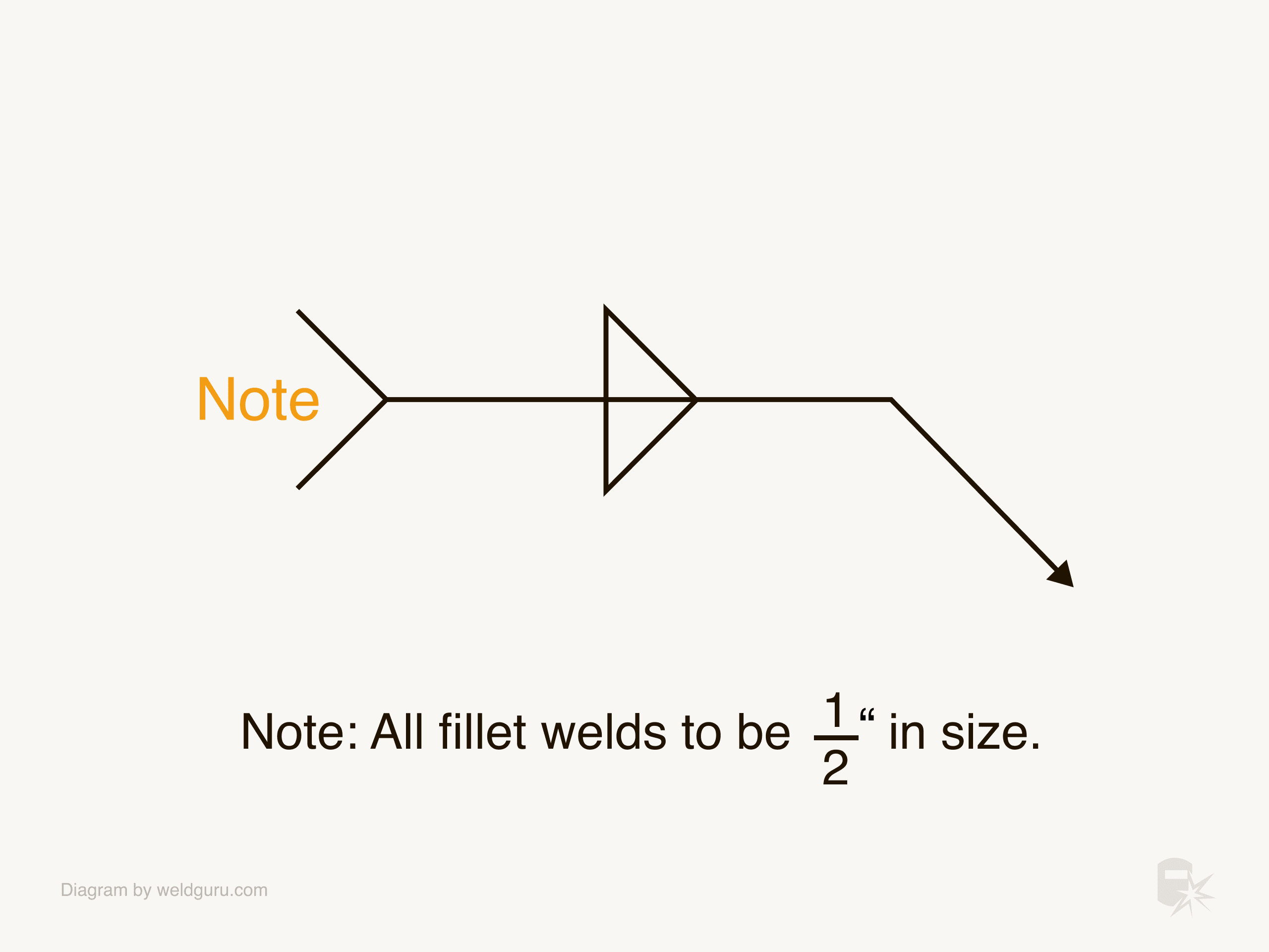
While inside the welding symbol is the more common place to specify the weld size, you may find this information elsewhere.
Occasionally, you’ll see a reference to a note on the drawing in the welding symbol’s tail.
Defining the Length of the Weld
Most fillet welds will be continuous along the length of a weld joint no matter how long it is. These welds are continuous. You’ll notice this if there is no dimension stated.
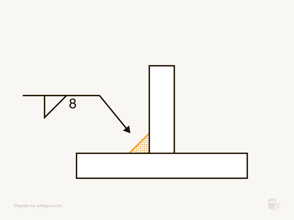
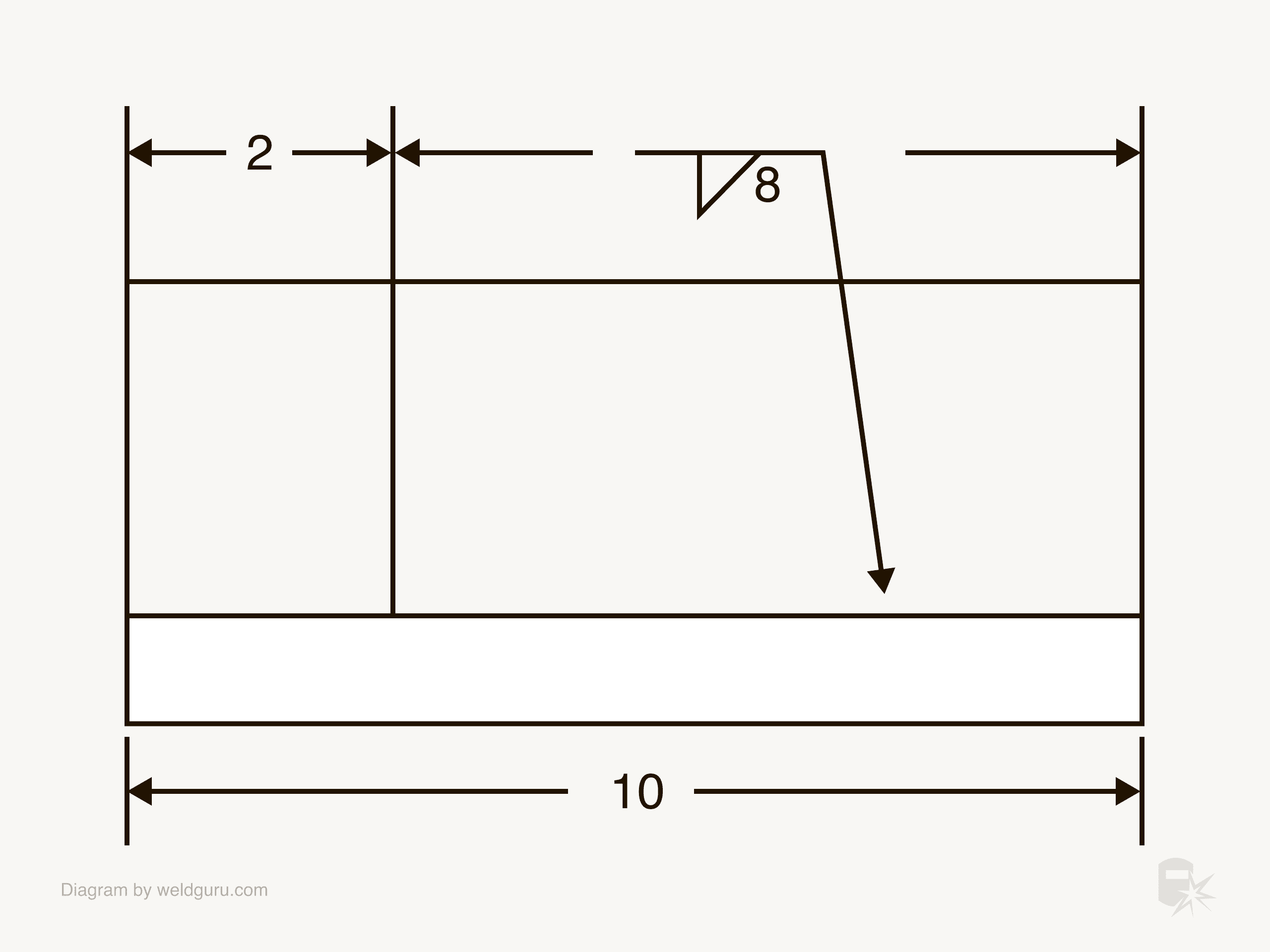
If the weld needs to be of a specific length, you’ll see a dimension to the right of the weld symbol. This dimension is the length of the fillet weld.
© weldguru.com – Image usage rights
In this example, the weld must be on the arrow side of the joint and be 8 inches long. There are several ways to tell you which part of the weld joint needs the weld.
© weldguru.com – Image usage rights
One method is to indicate where the weld should go using dimension lines, as in the example above.
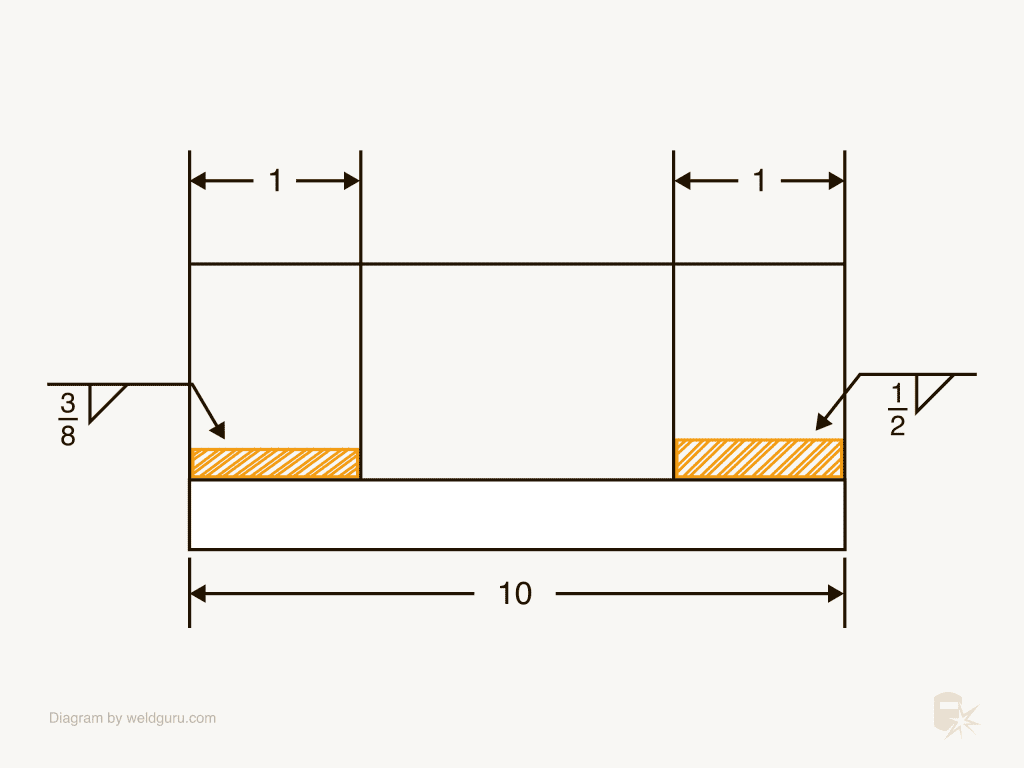
© weldguru.com – Image usage rights
Another way is to use hash-marked areas to show you where the weld goes and a welding symbol to tell you what type of weld goes there.
Locating the Weld on the Joint
Continuous welds will be along the joint the welding symbol arrow points to. When the weld needs to be in specific locations, you’ll have to pay close attention to the information on the drawing.
You’ll see either dimension lines or hash marks, which will tell you the weld locations on the joint.
Special Cases: Change of Direction and Multiple Arrows
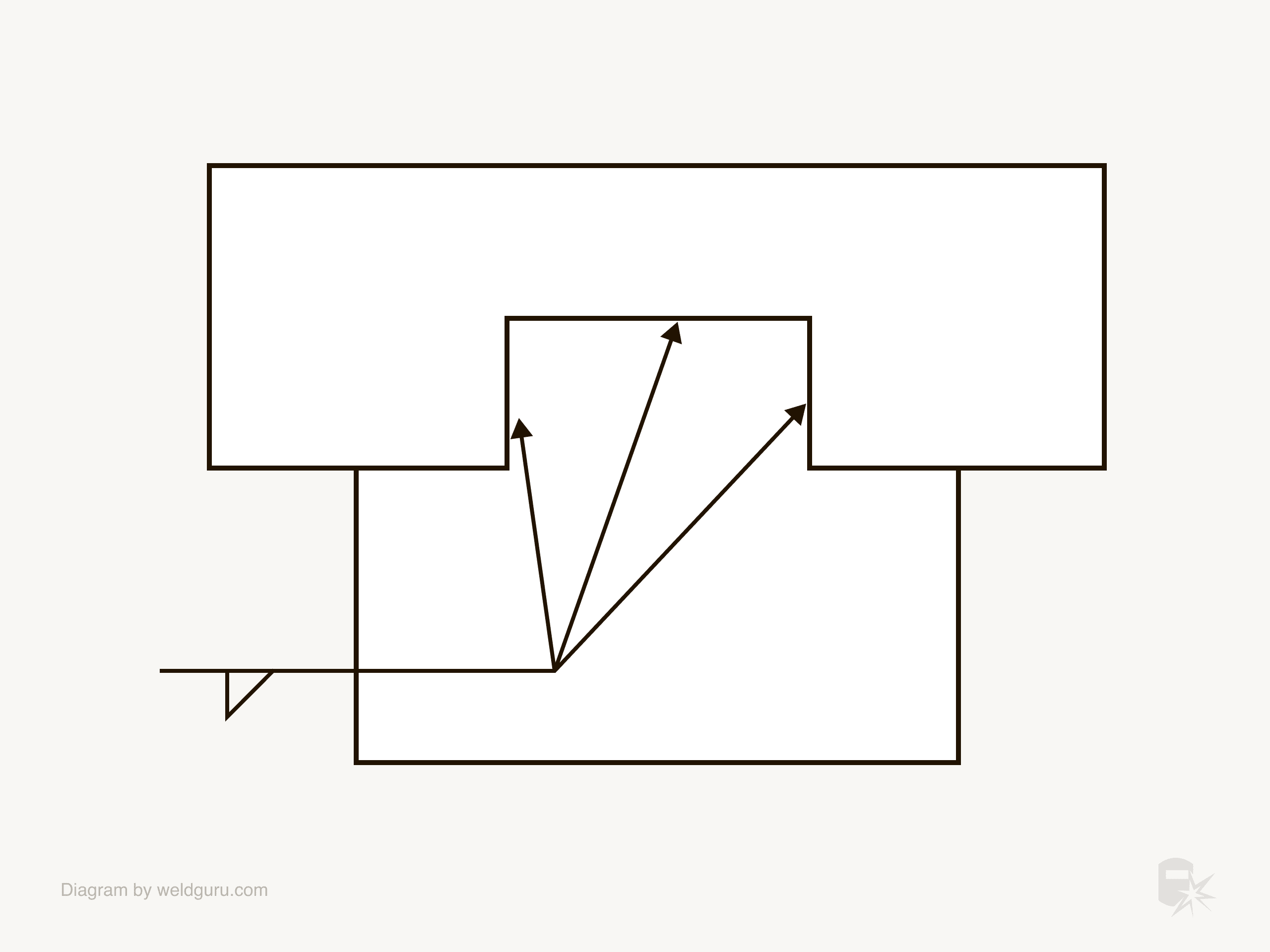
© weldguru.com – Image usage rights
There are cases where the weld will change direction around the part. Instead of using many weld symbols, you’ll see multiple arrows telling you to make the same weld to those areas of the weld joint.
In the case of a weld that is all around a part, you’ll see an all-around weld symbol shown above.
Intermittent Fillet Welds: Understanding Gaps & Segments
Sometimes, you’ll need to weld a series of smaller welds along a joint instead of a continuous weld. These are intermittent welds; the information you’ll need to weld these is next to the fillet weld symbol.
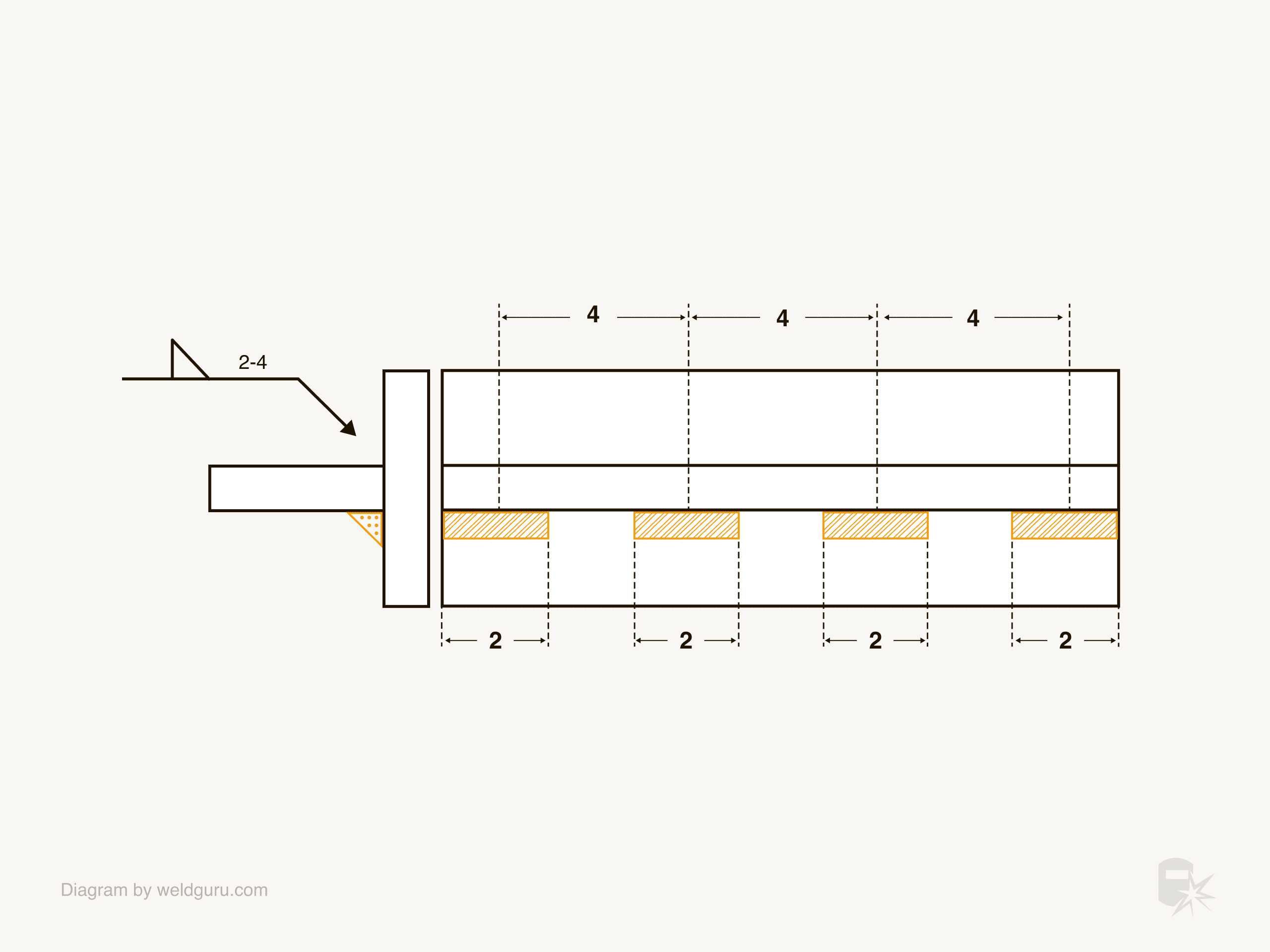
© weldguru.com – Image usage rights
When you need to use intermittent welds, you’ll see two numbers to the right of the weld symbol. The first number is the length of each weld, and the second number is the distance between the welds, which is the pitch of the welds.
The pitch of the welds is the distance between the center of each weld, not the space between them.
Chain Intermittent Welds
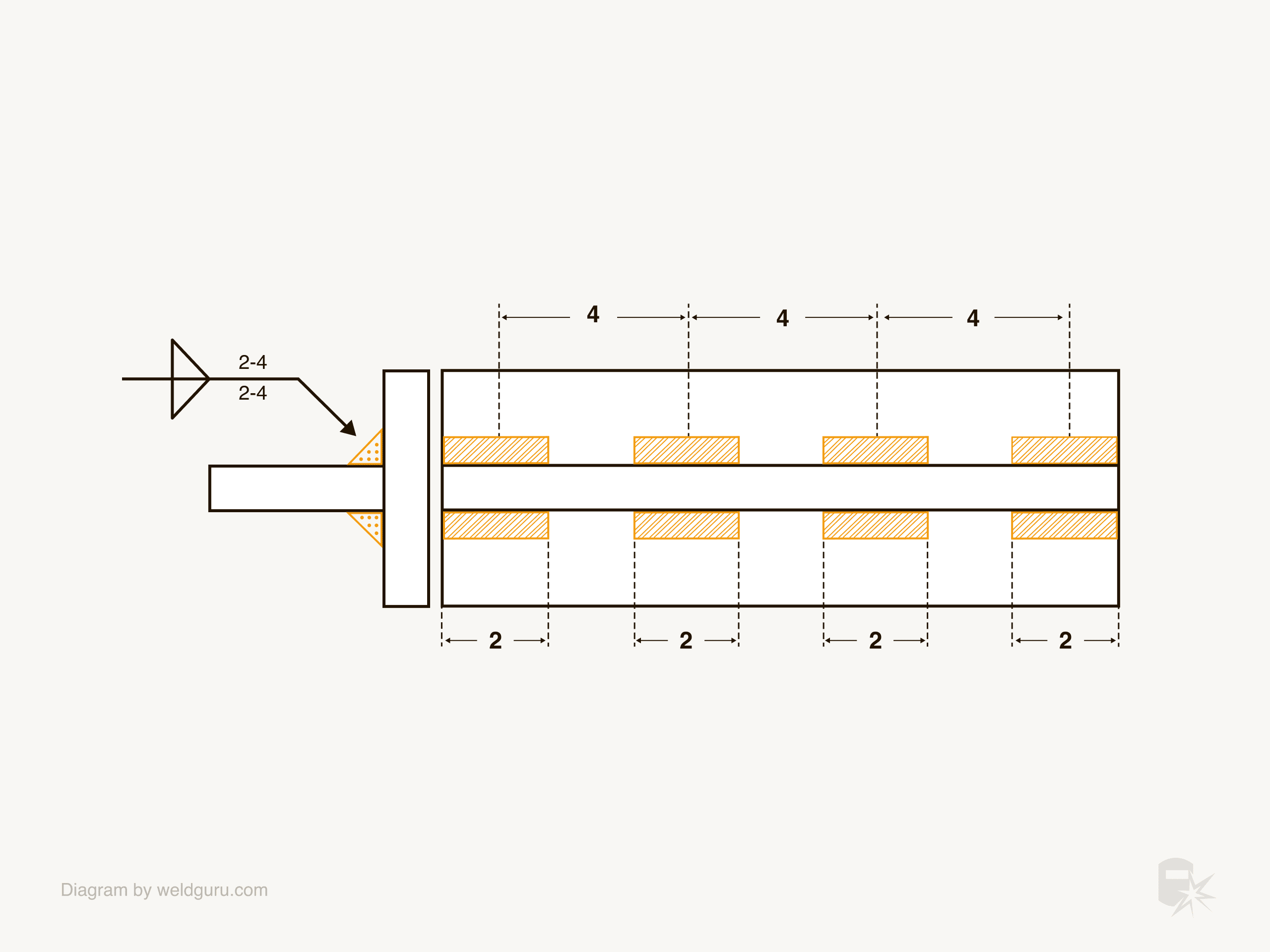
© weldguru.com – Image usage rights
When the intermittent weld is on both sides of the weld joint, it’s a chain intermittent weld.
Even if the length and pitch of the weld are the same for each side of the joint, you’ll see the pitch listed for each side of the weld joint.
Staggered Intermittent Fillet Welds
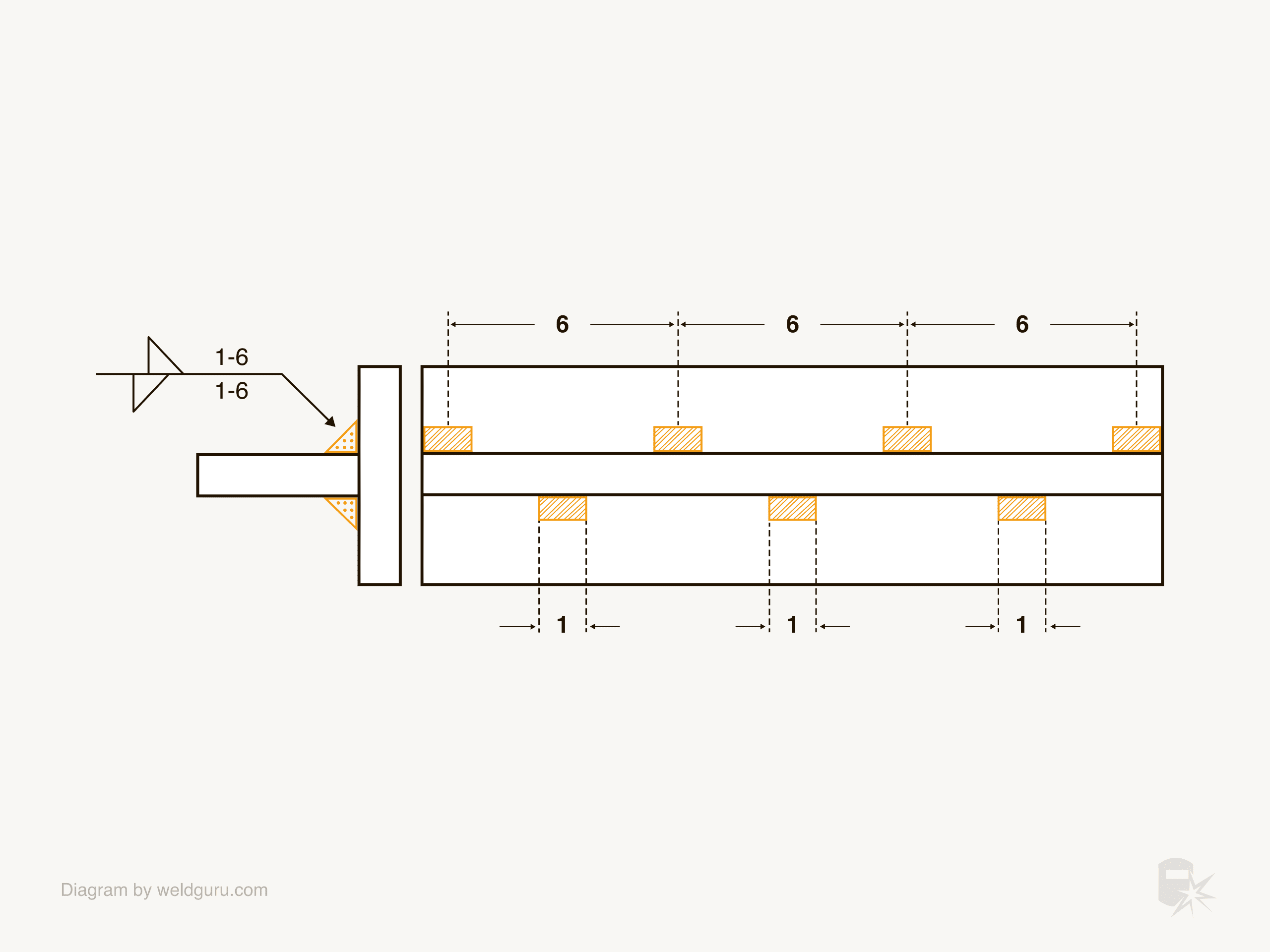
© weldguru.com – Image usage rights
When an intermittent weld is on both sides of the weld joint but offsets each other, it’s a staggered intermittent weld.
The weld symbols on the reference line will sit offset from each other, and each symbol will have the length and pitch next to it.
Mixing Continuous and Intermittent Welding
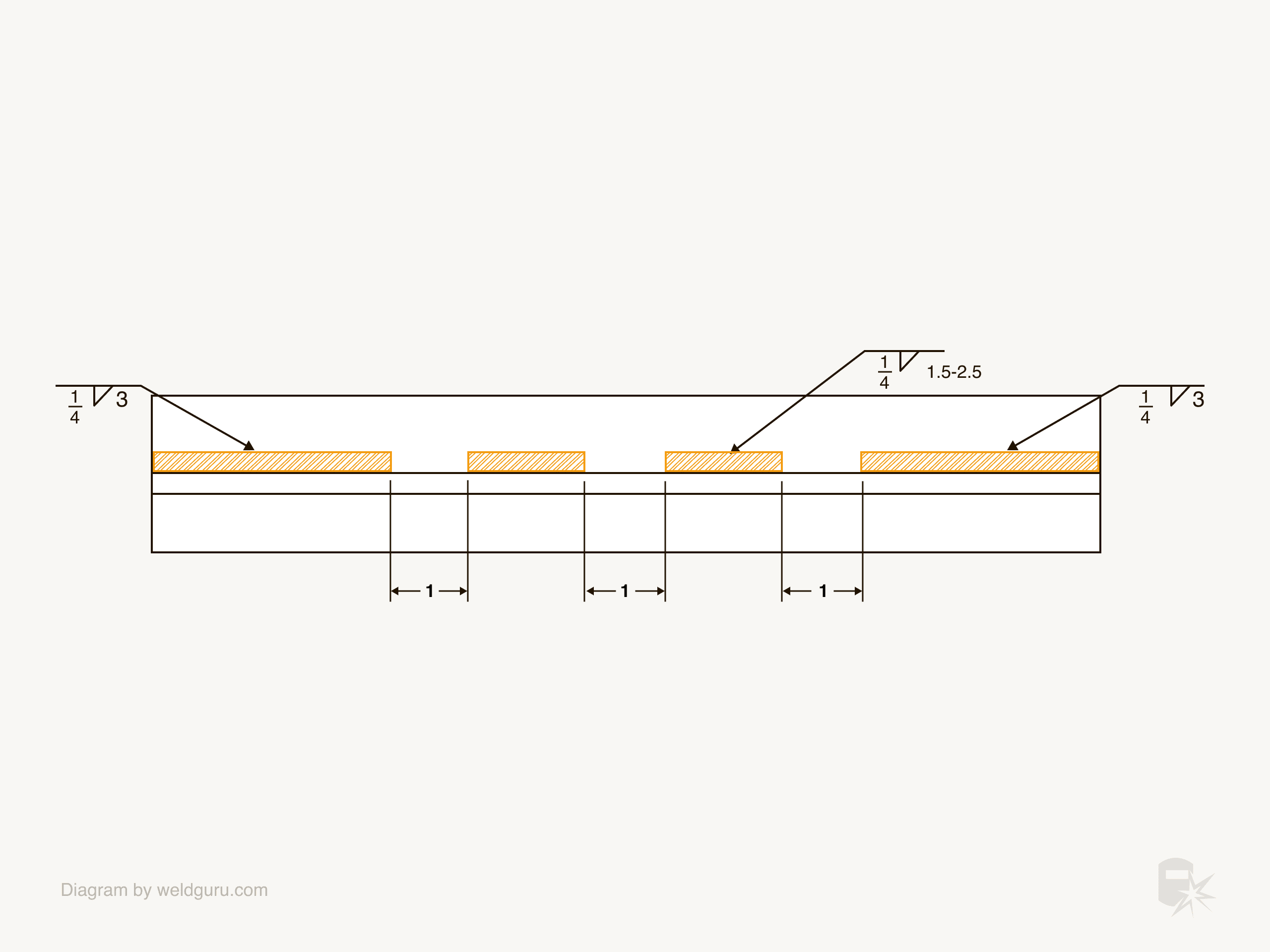
© weldguru.com – Image usage rights
You’ll see a welding symbol for each weld if you use continuous and intermittent welding along one weld joint.
The example above shows a 3” weld from either end of the weld joint and an intermittent weld between them.
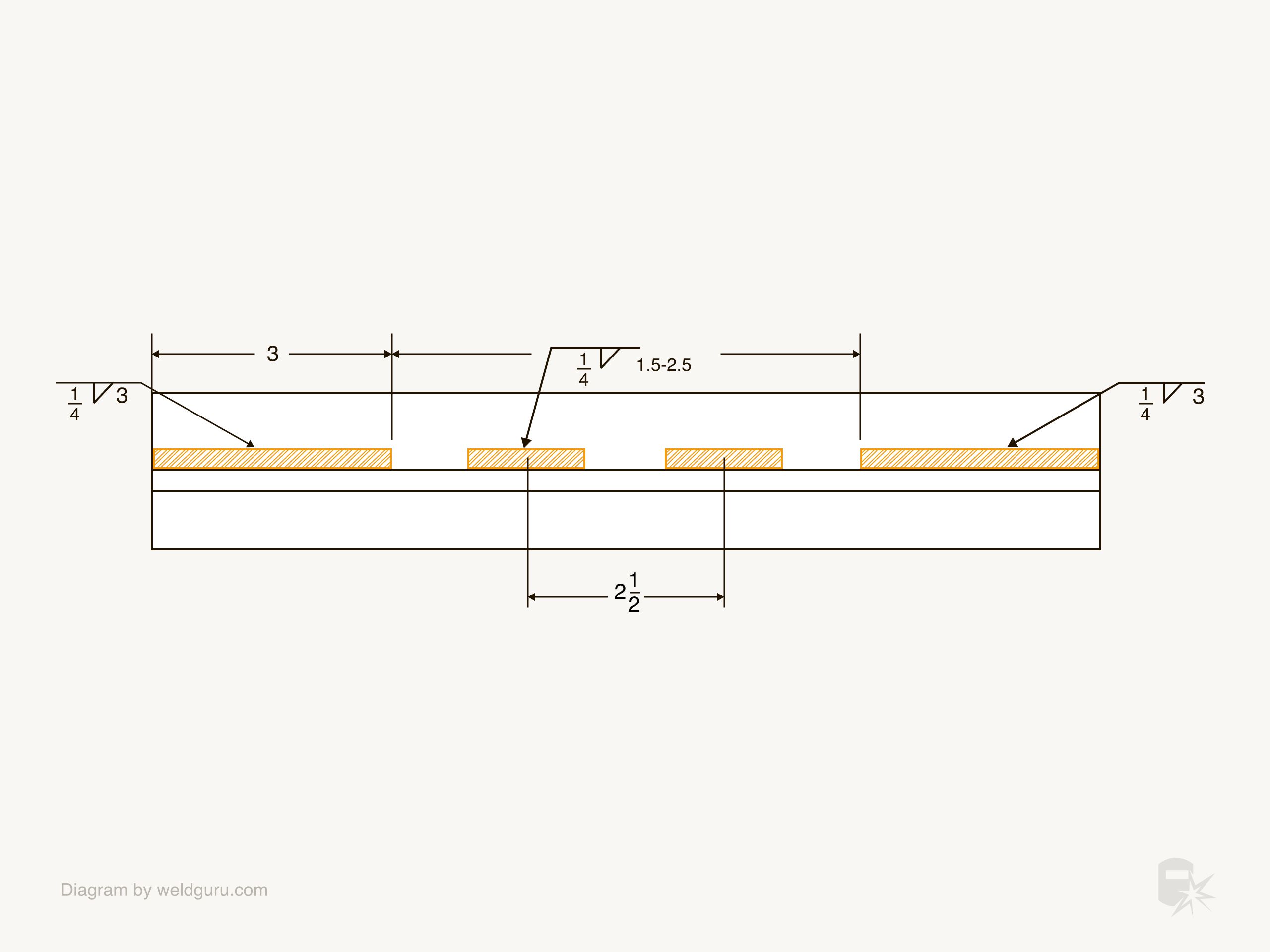
© weldguru.com – Image usage rights
They’re expressed using dimension lines to make the layout of continuous and intermittent welds more straightforward. The example image above illustrates this quite well.
Calculating the Spacing Between Welds
You measure the pitch of an intermittent weld from the center of one weld to the center of the next weld. The problem with this is that it makes the layout more difficult.
It’s much simpler to lay out the welds if you know the distance from the end of one weld to the start of the next.
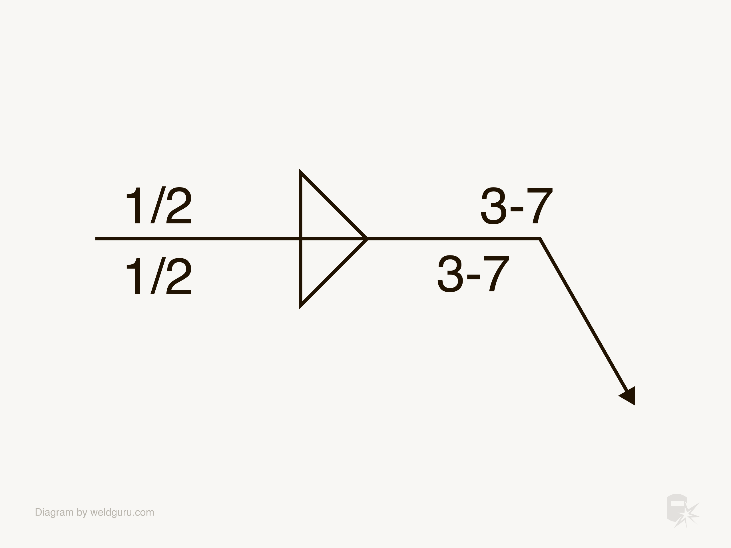
To get this dimension, you’ll need to do some simple math. Take the pitch of the weld and subtract the length of one weld; this gives you the dimension of the gap between welds.
© weldguru.com – Image usage rights
In this example, the welding symbol calls for a three-inch weld with a seven-inch pitch. You subtract the three-inch weld from the seven-inch pitch to determine the gap between the welds.
7-inch pitch – 3-inch weld = 4-inch gap
The result is a gap of four inches between the welds.
Supplementary Weld Symbols
You might see several supplementary weld symbols on a fillet welding symbol. These symbols give you extra information beyond length, pitch, and size, which is important to successfully welding the part.
All Around – You’ll see an all-around welding symbol when the weld needs to go around the perimeter of the piece. The all-around symbol is a circle on the point where the reference line becomes the arrow.
Field Weld – When a weld is to take place in the field rather than during the initial manufacturing, you’ll see a field weld symbol where the reference line breaks and becomes the arrow. The field weld symbol is a flag that sticks up from the point where the reference line becomes the arrow.
Flat Contour Finish – When the finished weld needs a flat finish, you’ll see a flat contour symbol and usually a process symbol. The contour symbol is a flat line along the face of the fillet weld symbol.
The process symbol is a letter telling you which method to use to achieve the contour.
Examples of process method symbols are:
- C = chipping
- G = grinding
- H = hammering
- M = machining
- R = rolling
- U = unspecified
These processes are not exclusive to the flat contour; you can also use them for the convex and concave profiles.
Convex Contour Finish – If the weld needs to be convex in profile, the weld symbol will have a convex contour symbol. The convex contour symbol is an outwardly curved line along the face of the fillet weld symbol.
Concave Contour Finish – Sometimes, the weld must be concave in profile. In this case, you’ll see a concave contour symbol. The concave contour symbol is a curved line that curves inwards toward the face of the fillet weld symbol.
Wrapping It Up
As a welder, you’ll see a lot of fillet weld symbols. These are some of the most common symbols that welders encounter, and an in-depth understanding of their anatomy is critical.
I’ve seen many parts rejected because the welder misunderstood the required fillet weld’s size, length, or pitch. In-depth knowledge of fillet weld symbols will ensure you know exactly what to do.