There are three oxy-acetylene methods used that dictate where the flame is placed in relation to the weld.
Each is described in detail below including descriptions and illustrations of the forehand (leave the weld behind you and move right to left for right-handed people), backhand (flame directed toward the completed weld) and the fillet (weld of approximately triangular cross section, as used in a lap joint, joining two surfaces at approximately right angles to each other).

Forehand Welding
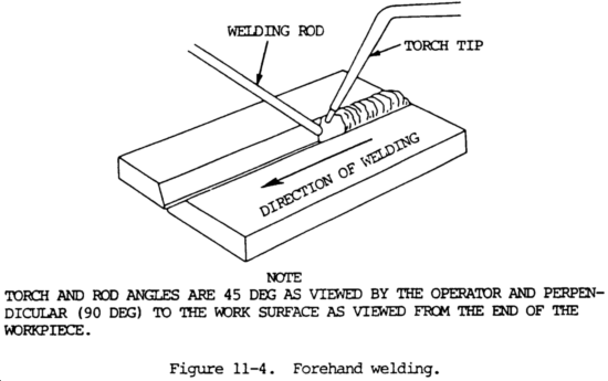
In this method, the welding rod precedes the torch. The torch is held at approximately a 45 degree angle from the vertical in the direction of welding, as shown in figure 11-4. The flame is pointed in the direction of welding and directed between the rod and the molten puddle. This position permits uniform preheating of the plate edges immediately ahead of the molten puddle. By moving the torch and the rod in opposite semicircular paths, the heat can be carefully balanced to melt the end of the rod and the side walls of the plate into a uniformly distributed molten puddle. The rod is dipped into the leading edge of the puddle so that enough filler metal is melted to produce an even weld joint. The heat which is reflected backwards from the rod keeps the metal molten. The metal is distributed evenly to both edges being welded by the motion of the tip.
In general, the forehand method is recommended for welding material up to 1/8 in. (3.2 mm) thick, because it provides better control of the small weld puddle, resulting in a smoother weld at both top and bottom. The puddle of molten metal is small and easily controlled. A great deal of pipe welding is done using the forehand technique, even in 3/8 in. (9.5 mm) wall thick-nesses. In contrast, some difficulties in welding heavier plates using the forehand method are:
The edges of the plate must be beveled to provide a wide V with a 90 degree included angle. This edge preparation is necessary to ensure satisfactory melting of the plate edges, good penetration, and fusion of the weld metal to the base metal.
Because of this wide V, a relatively large molten puddle is required. It is difficult to obtain a good joint when the puddle is too large.

Backhand Welding Method
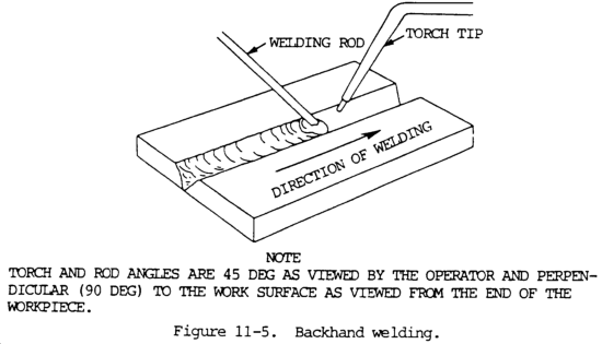
In the backhand welding method, the torch precedes the welding rod, as shown in figure 11-5.
The torch is held at approximately a 45 degree angle from the vertical away from the direction of welding, with the flame directed at the molten puddle.
The welding rod is between the flame and the molten puddle.
This position requires less transverse motion than is used in forehand welding.
Backhand Welding Illustration

Increased speeds and better control of the puddle are possible with backhand technique when metal 1/8 in. (3.2 mm) and thicker is welded, based on the study of speeds normally achieved with this technique and on greater ease of obtaining fusion at the weld root.
Backhand welding may be used with a slightly reducing flame (slight acetylene feather) when desirable to melt a minimum amount of steel in making a joint.
The increased carbon content obtained from this flame lowers the melting point of a thin layer of steel and increases welding speed.
This technique increases the speed of making pipe joints where the wall thickness is 1/4 to 5/16 in. (6.4 to 7.9 mm) and groove angle is less than normal.
Backhand welding is sometimes used in surfacing operations.

Fillet Welding
Fillet is the most popular of all types of welding methods because there is normally no preparation required.
In some cases, the fillet weld is the least expensive, even though it might require more filler metal than a groove weld since the preparation cost would be less.
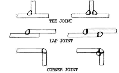
It can be used for the lap joint, the tee joint, and the corner joint without preparation.
Since these are extremely popular, the fillet has wide usage.
On corner joints, the double fillet can actually produce a full-penetration weld joint.
The use of the fillet for making all five of the basic joints is shown in the figure below.
Fillet welds are also used in conjunction with groove welds, particularly for corner and tee joints.
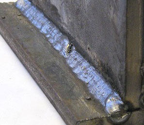
Fillet Welding Illustration

The fillet weld is expected to have equal length legs and thus the face of the fillet is on a 45 degree angle. This is not always so, since a fillet may be designed to have a longer base than height, in which case it is specified by the two leg lengths.
On the 45 degree or normal type of fillet, the strength of the fillet is based on the shortest or throat dimension which is 0.707 x the leg length. For fillets having unequal legs, the throat length must be calculated and is the shortest distance between the root of the fillet and the theoretical face of the fillet. In calculating the strength of fillet welds, the reinforcement is ignored. The root penetration is also ignored unless a deep penetrating process is used. If semi-or fully-automatic application is used, the extra penetration can be considered.
Under these circumstances, the size of the fillet can be reduced, yet equal strength will result. Such reductions can be utilized only when strict welding procedures are enforced. The strength of the fillet weld is determined by its failure area, which relates to the throat dimension. Doubling the size or leg length of a fillet will double its strength since it doubles the throat dimension and area. However, doubling the fillet size will increase its cross-sectional area and weight four times. For example, a 3/8 in. (9.5 mm) fillet is twice as strong as a 3/16 in. (4.8 mm) fillet; however, the 3/8 in. (9.5 mm) fillet requires four times as much weld metal.
In design work, the fillet size is sometimes governed by the thickness of the metals joined. In some situations, the minimum size of the fillet must be based on practical reasons rather than the theoretical need of the design. Intermittent fillets are sometimes used when the size is minimum, based on code, or for practical reasons, rather than because of strength requirements. Many intermittent welds are based on a pitch and length so that the weld metal is reduced in half. Large intermittent fillets are not recommended because of the volume-throat dimension relationship mentioned previously. For example, a 3/8 in. (9.5 mm) fillet 6 in. (152.4 mm) long on a 12 in. (304.8 mm) pitch (center to center of intermittent welds) could be reduced to a continuous 3/16 in. (4.8 mm) fillet, and the strength would be the same, but the amount of weld metal would be only half as much.
Single fillet welds are extremely vulnerable to cracking if the root of the weld is subjected to tension loading. This applies to tee joints, corner joints, and lap joints. The simple remedy for such joints is to make double fillets, which prohibit the tensile load from being applied to the root of the fillet. This is shown by figure 11-6. Notice the F (force) arrowhead.
A different welding technique is required for fillet welding than for butt joints because of the position of the parts to be welded. When welding is done in the horizontal position, there is a tendency for the top plate to melt before the bottom plate because of heat rising. This can be avoided, however, by pointing the flame more at the bottom plate than at the edge of the upper plate. Both plates must reach the welding temperature at the same time.
In making the weld, a modified form of backhand technique should be used. The welding rod should be kept in the puddle between the completed portion of the weld and the flame. The flame should be pointed ahead slightly in the direction in which the weld is being made and directed at the lower plate. To start welding, the flame should be concentrated on the lower plate until the metal is quite red. Then the flame should be directed so as to bring both plates to the welding temperature at the same time. It is important that the flame not be pointed directly at the inner corner of the fillet. This will cause an excessive amount of heat to build up and make the puddle difficult to control.
It is essential in this form of welding that fusion is obtained at the inside corner or root of the joint.