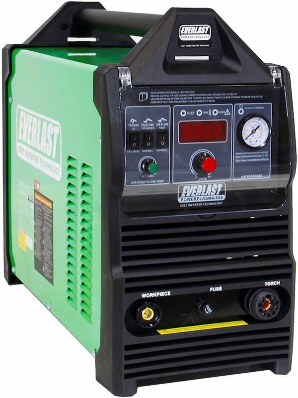
Plasma and the plasma arc cutting process uses heated gas to cut through metal (30,000 degrees Fahrenheit).
The process works by heating gas to temperatures that cause it to ionize or conduct electricity. The gas is pressurized and shot over a tungsten electrode.
The plasma cutting machine adds electricity which forms a circuit with the metal to be cut.
The process produces heat which turns the gas into plasma, which can cut metal.
The process can be used to both cut and gouge metal. When gouging the process offers lower cost, lower fume and noise levels vs. carbon arc gouging.
The machine is relatively easy to use… Check the gas lines and connections, turn on the air compressor (for air-cooled models) and then turn on the power.
Easy!
Overview
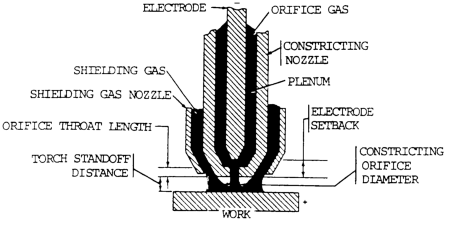
The plasma arc cutting process cuts metal by melting a section of metal with a constricted arc. A high-velocity jet flow of hot ionized gas melts the metal and then removes the molten material to form a kerf. The basic arrangement for a plasma arc cutting torch, similar to the plasma arc welding torch, is shown in figure 10-71.
Three variations of the process exist:
- low current plasma cutting
- high current plasma cutting
- cutting with water added
Low current arc cutting, which produces high-quality cuts of thin materials, uses a maximum of 100 amperes and a much smaller torch than the high current version. Modifications of processes and equipment have been developed to permit the use of oxygen in the orifice gas to allow efficient cutting of steel.
All plasma torches constrict the arc by passing it through an orifice as it travels away from the electrode toward the workpiece. As the orifice gas passes through the arc, it is heated rapidly to a high temperature, expands and accelerates as it passes through the constricting orifice. The intensity and velocity of the arc plasma gas are determined by such variables as the type of orifice gas and its entrance pressure, constricting orifice shape and diameter, and the plasma energy density on the work.
Advantages and Disadvantages
Advantages
There are many advantages to the plasma arc cutting process:
-
- Small risk of changing the shape of the metal (called distortion)
- Precise cutting
- Slag-free cuts when working with aluminum, stainless steel and carbon steel
- Works in all positions
- Fast process
- Works across many types of metals
- Do not require gas cylinders
Disadvantages
Some disadvantages of plasma arc cutting:
- Creates a small bevel (7 degrees – approximate)
- Electrical shock risk when not operating safely
- Requires a clean air source – some now come compressors built in
- Needs electricity to operate so not completely portable
- Not cost-effective for very thick steel
Plasma Arc Cutting Operation
The basic plasma arc cutting circuitry is shown in figure 10-72. The process operates on direct current, straight polarity (dcsp), electrode negative, with a constricted transferred arc.
In the transferred arc mode, an arc is struck between the electrode in the torch and the workpiece. The arc is initiated by a pilot arc between the electrode and the constricting nozzle. The nozzle is connected to ground (positive) through a current limiting resistor and a pilot arc relay contact.
The pilot arc is initiated by a high-frequency generator connected to the electrode and nozzle. The welding power supply then maintains this low current arc inside the torch. Ionized orifice gas from the pilot arc is blown through the constricting nozzle orifice.
This forms a low resistance path to ignite the main arc between the electrode and the workpiece.
When the main arc ignites, the pilot arc relay may be opened automatically to avoid unnecessary heating of the constricting nozzle.
Principles of Operation
The basic plasma arc cutting circuitry is shown in figure 10-72. The process operates on direct current, straight polarity (dcsp), electrode negative, with a constricted transferred arc. In the transferred arc mode, an arc is struck between the electrode in the torch and the workpiece. The arc is initiated by a pilot arc between the electrode and the constricting nozzle. The nozzle is connected to ground (positive) through a current limiting resistor and a pilot arc relay contact. The pilot arc is initiated by a high-frequency generator connected to the electrode and nozzle.
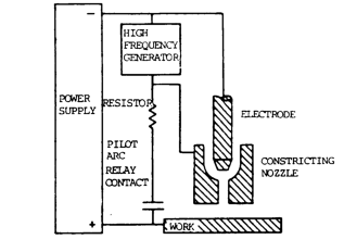
The welding power supply then maintains this low current arc inside the torch. Ionized orifice gas from the pilot arc is blown through the constricting nozzle orifice. This forms a low resistance path to ignite the main arc between the electrode and the workpiece. When the main arc ignites, the pilot arc relay may be opened automatically to avoid unnecessary heating of the constricting nozzle.
Because the plasma constricting nozzle is exposed to the high plasma flare temperatures (estimated at 18,032 to 25,232°F (10,000 to 14,000°C)), the nozzle must be made of water-cooled copper. In addition, the torch should be designed to produce a boundary layer of gas between the plasma and the nozzle.
Related read: Plasma cutting gases – Selection guide
Torches
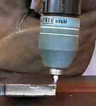
Plasma cutting torches will fit torch holders in automatic flame cutting machines.
As a guideline, when starting the plasma arc cutting torch, place the tip 1/4″ above the plate. Do not touch the plate (follow manufacturers’ directions).
Always start at the edge with some metal under the tip.
High Current Cutting
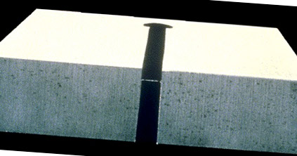
For high current cutting, the torch is mounted on a mechanical carriage. Automatic shape cutting can be done with the same equipment used for oxygen cutting, if sufficiently high travel speed is attainable. A water spray is used surrounding the plasma to reduce smoke and noise. Work tables containing water which is in contact with the underside of the metal being cut will also reduce noise and smoke.
Cutting Positions
The plasma arc cutting torch can be used in all positions. It can also be used for piercing holes and for gouging. The cutting torch is of special design for cutting and is not used for welding.
If used in positions that are not flat, use low-power plasma machines at less than 100 amps. Higher power machines can be dangerous when out of the flat position.
Procedures
The operating procedures for plasma arc cutting is as follows (check the manufacturer instructions for your specific unit, these are general guidelines):
- Check the air pressure (should be about 70 p.s.i.).
- Attached the ground clamp to the metal being cut
- Turn the cutting on
- Adjust amperage to the manufacturers specification for the metal and metal thickness
- Position shielding cut over metal
- Press the ignition button and establish the arc
- Move arc over cut line and cut. Consider using a guide bar if needed, which will help make a straighter cut. Hold the shielding cup and constricting nozzle 1/8″ to 1/4″ above the surface being cut. Do not drag the shielding cup and constricting nozzle on the metal unless they are designed to be used in this way.Tip: Make the cut on the waste side of the cut line.
- Use a slower travel speed for thicker metal. The direction of cutter (sideways, backward, forward) is at the option of the cutter.
- Move the cutter as quickly as possible.
- If using compressed air, make sure it is free of moisture. There is an air filter available for the line that can condition the air for improved plasma arc cutting quality.
Metals
The metals usually cut with this process are the aluminum and stainless steel. The process can also be used for cutting most iron-free metals (non-ferrous) as well as:
- aluminum
- brass
- carbon steels
- cast iron
- copper alloys
- copper
- high nickel
- magnesium
- mild steel
- nickel alloys
- stainless steel
Controls
Special controls are required to adjust both plasma and secondary gas flow. Torch-cooling water is required and is monitored by pressure or flow switches for torch protection. The cooling system should be self-contained, which includes a circulating pump and a heat exchanger.
Process Variations
Several process variations are used to improve the PAC quality for particular applications. They are generally applicable to materials in the 1/8 to 1-1/2 in. (3 to 38 mm) thickness range. Auxiliary shielding, in the form of gas or water, is used to improve cutting quality.
Dual Flow Plasma Cutting
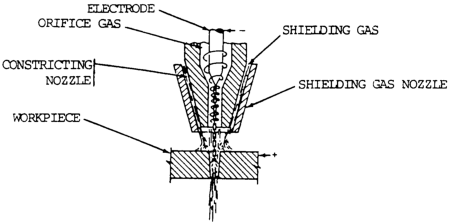
Dual flow plasma cutting provides a secondary gas blanket around the arc plasma, as shown in figure 10-73. The usual orifice gas is nitrogen. The shielding gas is selected for the material to be cut. For mild steel, it may be carbon dioxide (CO2) or air; for stainless steals, CO2; and an argon-hydrogen mixture for aluminum. For mild steel, cutting speeds are slightly faster than with conventional plasma arc cutting, but the cut quality is not satisfactory for many applications.
Water Shield Plasma Cutting
This technique is similar to dual flow plasma cutting. Water is used in place of the auxiliary shielding gas. Cut appearance and nozzle life are improved by the use of water in place of gas for auxiliary shielding. Cut squareness and cutting speed are not significantly improved over conventional PAC.
Water Injection Plasma Cutting
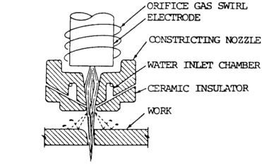
This modification of the PAC process uses a symmetrical impinging water jet near the constricting nozzle orifice to further constrict the plasma flame. The arrangement is shown in figure 10-74. The water jet also shields the plasma from mixing with the surrounding atmosphere. The end of the nozzle can be made of ceramic, which helps to prevent double arcing. The water constricted plasma produces a narrow, sharply defined cut at speeds above those of conventional PAC. Because most of the water leaves the nozzle as a liquid spray, it cools the kerf edge, producing a sharp corner. The kerf is clean. When the orifice gas and water are injected in tangent, the plasma gas swirls as it emerges from the nozzle and water jet. This can produce a high-quality perpendicular face on one side of the kerf. The other side of the kerf is beveled. In shape cutting applications, the direction of travel must be selected to produce a perpendicular cut on the part and the bevel cut on the scrap.
Ventilation
The amount of gases and tines generated requires the use of local exhaust for proper ventilation. Cutting should be done over a water reservoir so that the particles removed from the cut will fall in the water. This will help reduce the amount of fumes released into the air.
If cutting over an object that can blowback the plume, such as a barrel, use caution or avoid the situation completely.
Applications
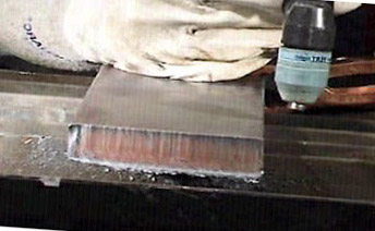
Plasma arc cutting can be used to cut any metal. Most applications are for:
- carbon steel
- aluminum
- stainless steel
It can be used for stack cutting, plate beveling, shape cutting, and piercing.
Safety Warnings
Ear protection must be worn when working with high-powered equipment. The noise level generated by the high-powered equipment is uncomfortable. The cutter must wear ear protection.
The normal protective clothing to protect the cutter from the arc must also be worn. This involves protective clothing, gloves, and helmet.
The passive welding helmet should be equipped with a shade no. 9 filter glass lens. Alternatively, you should be wearing an auto darkening helmet.
There are many applications for low-current plasma arc cutting, including the cutting of stainless and aluminum for production and maintenance. Plasma cutting can also be used for stack cutting and it is more efficient than stack cutting with the oxyacetylene torch. Low current plasma gouging can also be used for upgrading castings.
Avoid cutting in areas that are wet or damp as this increases the risk of electric shock.
Use higher power machines (over 100 amps) in flat positions. Check with the manufacturer for exact specifications.
Troubleshooting
The quality of the plasma arc cutting process can decline if:
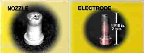
- the electrode needs to be changed (electrodes last 2x the life of the constricting nozzle)
- the constricting nozzle is worn out