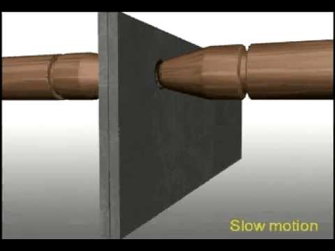
What is Resistance Welding
Resistance welding is a group of thermo-electric processes in which coalescence is produced by the heat obtained from resistance of the work to electric current in a circuit of which the work is a part and by the application of pressure.
Said another way, pressure is applied to the two overlapping sheets being joined. Electrical current is applied causing resistive heating, which results in the melting of metal and the formation of a weld. The weld is called a weld nugget.
There are at least seven important resistance-welding processes. These are:
- Flash welding
- High frequency
- Percussion welding
- Projection welding
- Resistance seam welding
- Resistance spot welding (most common process), involves the use of water-cooled copper electrodes which are clamped with the sheets into place. The electrical current is then applied to the electrodes causing the weld nugget to form.
- Upset welding
Applications of Resistance Welding
Resistance welding is used where long production runs and consistent conditions can be maintained.
Welding is performed with operators who normally load and unload the welding machine and operate the switch for initiating the weld operation.
The automotive industry is the major user of the resistance welding processes, followed by the appliance industry. Resistance welding is used by many industries manufacturing a variety of products made of thinner gauge metals.
This type of welding is also used in the steel industry for manufacturing pipe, tubing, and smaller structural sections.
It has the advantage of producing a high volume of work at high speeds and does not require filler materials. Welds are reproducible and high-quality welds are normal.
Resistance Welding Video
The Process of Resistance Welding
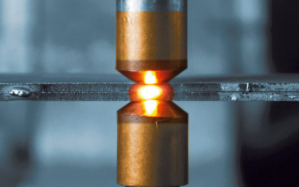
The resistance welding processes differ from many of the other more popular welding processes such as MIG, Stick and TIG. Filler metal is rarely used and fluxes are not employed.
Three factors involved are:
- The amount of current that passes through the work
- The pressure that the electrodes transfer to the work
- The time the current flows through the work.
Heat is generated by the passage of electrical current through a resistance circuit. The force applied before, during, and after the current flow forces the heated parts together so that coalescence will occur. Pressure is required throughout the entire welding cycle to assure a continuous electrical circuit through the work.
Resistance welds are made very quickly; however, each process has its own time cycle.
Resistance welding operations are automatic. The pressure is applied by mechanical, hydraulic, or pneumatic systems. Motion, when it is involved, is applied mechanically. Current control is completely automatic once the welding operator initiates the weld. Resistance welding equipment utilizes programmers for controlling current, time cycles, pressure, and movement. Welding programs for resistance welding can become quite complex. In view of this, quality welds do not depend on welding operator skill but more on the proper set up and adjustment of the equipment and adherence to weld schedules.
This concept of resistance welding is most easily understood by relating it to resistance spot welding. Resistance spot welding, the most popular, is shown in figure 10-77 below. High current at a low voltage flows through the circuit and is in accordance with Ohm’s law.
- (a) I is the current in amperes, E is the voltage in volts, and R is the resistance of the material in ohms. The total energy is expressed by the formula:
Energy = I x E x T in which T is the time in seconds during which current flows in the circuit. - (b) Combining these two equations gives H (heat energy) = 12 x R x T.
For practical reasons a factor which relates to heat losses should be included; therefore, the actual resistance welding formula is
H (heat energy) =I2 x R x T x K - (c) In this formula, I = current squared in amperes, R is the resistance of the work in ohms, T is the time of current flow in seconds, and K represents the heat losses through radiation and conduction.
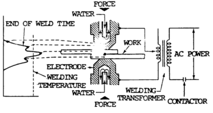
The resistive heating process occurs between the two pieces of metal. The current flows across the electrodes and metal, causing the formation of the weld nugget. When the welding current is turned off, the weld cools causing the welding nugget to become solid while joining the two pieces of metal.
Resistance spot welding is used extensively because it is a simple, inexpensive, versatile, and forgiving process. It has been shown to be adaptable to some degree of feedback control.
Resistance Seam Welding
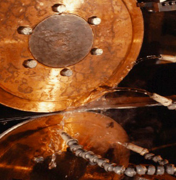
Resistance seam welding is a variation on resistance spot welding. The welding electrodes are motor-driven wheels rather than stationary caps. This results in a seam or rolling resistance weld. There are three independent parameters in configuring seam welding machines: sheet configuration, welding wheel configuration and the power supply.
The major concern with power supplies and control is the frequency with which current is applied to the workpiece. Depending on this frequency and the speed with which the material is being welded, the weld will be either a continuous seam weld, an overlapping seam weld, or a roll spot weld.
Overlapping or Continuous Seam welds are typically used to produce continuous gas- or water-tight joints in sheet assemblies, such as automotive gasoline tanks. The process is also used to weld longitudinal seams in structural tubular sections that do not require leak-tight seams. In most applications, two-wheel electrodes, or one translating wheel and a stationary mandrel, are used to provide the current and pressure for resistance seam welding.
How Resistance Welding Works
- Bulk Resistance: Metals have what is called a PTC or Positive Temperature Coefficient. This means that their resistance increases as temperature increases.
- Contact Resistance: When two surfaces come in contact, microscopically the surfaces are rough, where some points come in contact on the surface and some do not. At the points where contact is made and assuming the two pieces of metal are pressed together with some pressure, the oxide layer breaks forming a limited number of metal-to-metal bridges. The weld current is then passed over a large area as it moves through the bulk metal. Since the current is forced through a limited number of bridges this “necking down” increases the current density, generating heat which causes melting. As melting occurs, new bridges are formed. Molten metal also has a higher resistance than non-molten metal, forcing the current toward newer bridges. The process proceeds until the entire surface is molten. When the electrical current is turned off, the electrodes cool first, which then cools the molten metal. When everything solidifies the weld is formed.
Weldability
Weldability is controlled by three factors:
- Resistivity
- Thermal conductivity
- Melting temperature.
Metals with high resistance to current flow and with low thermal conductivity and a relatively low melting temperature would be easily weldable. Ferrous metals all fall into this category.
Metals that have a lower resistivity but a higher thermal conductivity will be slightly more difficult to weld. This includes light metals, aluminum and magnesium. The precious metals comprise the third group. These are difficult to weld because of very high thermal conductivity.
The fourth group is the refractory metals, which have extremely high melting points and are more difficult to weld.
These three properties can be combined into a formula that will provide an indication of the ease of welding metal. This formula is:
W = R / FKt x 100
In this formula:
- W equals weldability,
- R is resistivity
- F is the melting temperature of the metal in degrees C,
- Kt is the relative thermal conductivity with copper equal to 1.00.
If weldability (W) is below 0.25, it is a poor rating.
If W is between 0.25 and 0.75, weldability becomes fair.
Between 0.75 and 2.0, weldability is good.
Above 2.0 weldability is excellent.
In this formula, mild steel would have a weldability rating of over 10.
Aluminum has a weldability factor of from 1 to 2 depending on the alloy and these are considered having a good weldability rating.
Copper and certain brasses have a low weldability factor and are known to be very difficult to weld.
Welding Heat and Current
Welding heat is proportional to the square of the welding current. If the current is doubled, the heat generated is quadrupled. Welding heat is proportional to the total time of current flow, thus, if current is doubled, the time can be reduced considerably. The welding heat generated is directly proportional to the resistance and is related to the material being welded and the pressure applied. The heat losses should be held to a minimum. It is an advantage to shorten welding tire. Mechanical pressure which forces the parts together helps refine the grain structure of the weld.
Heat is also generated at the contact between the welding electrodes and the work. This amount of heat generated is lower since the resistance between high conductivity electrode material and the normally employed mild steel is less than that between two pieces of mild steel. In most applications, the electrodes are water-cooled to minimize the heat generated between the electrode and the work.
Positions
The position of making resistance welds is not a factor, particularly in the welding of thinner material.
Metals
Metals that are weldable, the thicknesses that can be welded, and joint design are related to specific resistance welding processes. Most of the common metals can be welded by many of the resistance welding processes (see table 10-72 below. Difficulties may be encountered when welding certain metals in thicker sections. Some metals require heat treatment after welding for satisfactory mechanical properties.
Base Metals Weldable by the Resistance Welding Process
| Base Metal | Weldability |
|---|---|
| Aluminums | weldable |
| Magnesium | weldable |
| Inconel | weldable |
| Nickel | weldable |
| Nickel silver | weldable |
| Monel | weldable |
| Precious metals | weldable |
| Low carbon steel | weldable |
| Low alloy steel | weldable |
| High & medium carbon | possible, not popular |
| Steel alloys | possible, not popular |
| Stainless Steel | weldable |
Electrodes in Resistance Welding
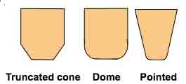
Electrodes vary by shape (called electrode geometry). The right electrode is selected in order to improve electrical-thermal-mechanical performance.
As the cross-sectional area increases rapidly with distance from the workpiece, thereby providing a good heat sink.
The diameter of the electrode contact area is a consideration; if the area is too small, it will produce undersized welds with insufficient strength; if the diameter of the electrode is too large, it will cause inconsistent and unstable weld growth characteristics.
The electrode must be able to:
- conduct current to the workpiece
- mechanically constrain the workpiece
- conduct heat from the workpiece
The materials used to construct the electrode has to sustain high loads at high temperatures while maintaining adequate electrical and thermal conductivity.
A range of copper-based or refractory-based electrode materials is used based on the application. Three groups of electrode materials are outlined below. Within each group, the Resistance Welding Manufacturers Association (RWMA) sorts electrode materials into classes.
- Group A contains copper-based alloys. Common examples are:Class 1: (99% copper, 1% cadmium; 60 KSI UTS (forged); conductivity 92% IACS) Specifically recommended, because of its high electrical and thermal conductivity, for spot welding aluminum alloys, magnesium alloys, brass and bronze.Class 2: (99.2% copper, 0.8% chromium; 62 ksi UTS (forged), 82% IACS) General purpose electrode material for production spot and seam welding of most materials.
- Group B contains refractory metals and refractory metal composites.
- Group C contains specialty materials such as dispersion-strengthened copper.
In general, higher levels of resistance occurs when the power supply overcomes the level of resistance. To produce higher levels of resistance dissimilar parts are used.
- Conductive electrodes such as copper are used to weld resistive materials like nickel or stainless steel
- Resistive electrodes such as those made from molybdenum are used for welding conductive metals such as gold or copper
Types of Bonds
- Stainless State Bond (also referred to as a therm-compression bond): Metals such as tungsten and molybdenum, which are dissimilar materials that have a dissimilar grain structure are joined together with high weld energy, short heating time and a high level of forces. When this occurs there isn’t much melting needed to form a bond. Peel strength is poor but tensile and shear strength is high.
- Fusion Bond: With this approach dissimilar or similar material that has similar grain structures are used. The metal is heated to the melting point of both metals. A “nugget” alloy of both materials is formed with larger grain growth. The bond formed has excellent shear strength, peel and tensile strengths.
- Reflow Braze Bond: In this approach, the resistance heating of gold, silver or other low-temperature brazing material is joined with either a widely varied thick/thin material or dissimilar materials. The brazing material must “wet” to each part and have a lower melting point than the two workpieces. The process requires a longer heating time (2 to 100ms) at low weld energy. The result is a bond with excellent tensile strength. The shear strength and peel is poor.
Advantages & Disadvantages of Resistance Welding
Advantages
- Higher speeds, <.1 seconds for automotive spot welding, short process time
- Excellent for sheet metal applications <1/4 inch
- No filler metals or consumables required
- Relatively safe due to low voltage requirements
- Environmentally friendly clean process
- Joint formed is reliable
The automotive and appliance industries choose resistance welding for manufacturing because of the great advantages this process has to offer.
The first advantage is speed. When over 5000 welds need to be made in a typical car, a process where each weld takes less than a second is of great importance. The process is also adaptable to robotic manipulation so the speed is extremely fast.
It is excellent for the sheet metals used in automotive construction, and because no filler metal is needed, the complex wire feed systems in many arc welding processes are avoided.
Disadvantages
- Power requirements
- Nondestructive testing
- Low fatigue and tensile strength
- Is not portable
- High levels of electrode wear
- If uses a lap joint, it requires additional metal
Several disadvantages are associated with this process. Resistance welding equipment is more expensive than arc welding equipment. The process lacks the portability of arc welding. Although individual spot welding guns may have limited movement on the assembly line, the power source is fixed.
Parts to be joined are limited to a thickness of less than 1/4 of an inch due to current requirements. Thicker base materials have a greater ability to dissipate heat away from the weld area. Also, the resistance welding process is limited to overlapping joints, which requires more material than a butt joint.
The process can produce unfavorable power line demands, particularly with single-phase as opposed to 3-phase transformers. Short time, high power demands can cause lights to dim and computers to reset if the electrical system in a factory is not properly prepared for the introduction of resistance welding equipment.
The lack of a simple, in-process nondestructive testing technique for resistance spot and seam welding is also a limitation. Because resistance welds are produced between overlapping sheets, there can be no visual examination if the finished weld. Also, the time required for ultrasonic inspection of individual spot welds would be unacceptable in a high production environment such as the automotive industry.
Spot welds have low tensile and fatigue strength; the notch around the periphery of the nugget between the sheets acts as a stress concentrator.
Electrode wear acts to increase the diameter of the electrode face. During production, current values must slowly rise to compensate for the decreased current density, else nugget size drops.
Resistance Welding Certification
The Resistance Welding Manufacturing Alliance and the American Welding Society are offering in beta testing a Resistance Welding Certification.
Certification is recommended for professionals in the fabrication or production of products that utilize resistance welding. The certification will confirm an understanding of the fundamentals of each of the resistance welding processes including:
- spot welding
- projection welding
- seam welding
- upset welding
- resistance brazing
- flash welding
- resistance heating
There is an education and experience requirement. To learn more visit the Resistance Welding Manufacturing Alliance.
