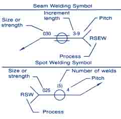
Resistance Spot Weld Symbol
Resistance spot weld symbols have no arrow or other side significance in themselves, although supplementary symbols used in conjunction with them may have such significance. Resistance spot weld symbols shall be centered on the reference line. Dimensions may be shown on either side of the reference line.
Weld Size
Resistance spot weld symbols are dimensioned by either size or strength as follows:
The size of resistance spot welds is designated as the diameter of the weld expressed in fractions or in decimals in hundredths of an inch and must be shown, with or without inch marks, to the left of the weld symbol (fig. 3-60).
Symbol for Size of Resistance Spot Welds

The strength of resistance spot welds is designated as the minimum acceptable shear strength in pounds per spot and must be shown to the left of the weld symbol (fig. 3-61).
Symbol for Strength of Resistance Spot Welds

Weld Pitch
The pitch of resistance spot welds shall be shown to the right of the weld symbol (fig. 3-62).
Weld Spacing
The pitch of resistance spot welds shall be shown to the right of the weld symbol (fig. 3-62).
Symbol for Spacing of Resistance Spot Welds

Number of Welds
When a definite number of welds is desired in a certain joint, the number must be shown in parentheses either above or below the weld symbol (fig. 3-64).
Symbol for Number of Resistance Spot Welds

Flush Resistance Spot Welding Joints
When the exposed surface of one member of a resistance spot welded joint is to be flush, that surface shall be indicated by adding the flush contour symbol to the weld symbol, (fig. 3-65) in accordance with location specifications.
Symbol for Contour of Resistance Spot Welds

Resistance Seam Weld Symbol
Resistance seam weld symbols have no arrow or other side significance in themselves, although supplementary symbols used in injunction with them may have such significance. Resistance seam weld symbols must be centered on the reference line.
Dimensions of resistance seam welds may be shown on either side of the reference line.
b. Size of Resistance Seam Welds. Resistance seam welds must be dimensioned by either size or strength as follows:
The size of resistance seam welds must be designated as the width of the weld expressed in fractions or in decimals in hundredths of an inch and shall be shown, with or without inch marks, to the left of the weld symbol (fig. 3-66).
Resistance Seam Weld Symbols Indicating Size

The strength of resistance seam welds must be designated as the minimum acceptable shear strength in pounds per linear inch and must be shown to the left of the weld symbol (fig. 3-67).
Resistance Seam Weld Symbols Indicating Strength

Length of Resistance Seam Welds
The length of a resistance seam weld, when indicated on the welding symbol, must be shown to the right of the welding symbol (fig. 3-68).
Resistance Seam Weld Symbols Indicating Length

When resistance seam welding extends for the full distance between abrupt changes in the direction of the welding, no length dimension need be shown on the welding symbol.
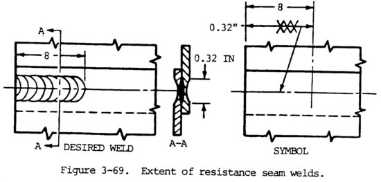
When resistance seam welding extends less than the distance between abrupt changes in the direction of the welding or less than the full length of the joint, the extent must be dimensioned (fig. 3-69).
Resistance Seam Weld Symbols Indicating Extent

Pitch
The pitch of intermittent resistance seam welding shall be designated as the distance between centers of the weld increments and must be shown to the right of the length dimension (fig. 3-70).
Dimensioning Symbols of Intermittent Resistance Seam Welds

Termination of Intermittent Resistance Seam Welding
When intermittent resistance seam welding is used by itself, the symbol indicates that increments are located at the ends of the dimensioned length. When used between continuous resistance seam welding, the symbol indicates that spaces equal to the pitch minus the length of one increment are left at the ends of the dimensional length. Separate symbols must be used for intermittent and continuous resistance seam welding when the two are combined.
Flush Projection Welded Joints
When the exposed surface of one member of a projection welded joint is to be made flush, that surface shall be indicated by adding the flush contour symbol to the weld symbol, observing the usual location significance (fig. 3-79).
Symbols Indicating Contour of Projection Welds

Related: What is Spot Welding?