TIG welding (GTAW) is a versatile process through which you can weld various metals. The biggest problem with TIG welding is that it requires more technique and skill than most welding processes.
These conditions can make it difficult for beginners to learn, which causes a lot of frustration.
You need to consider many things as you TIG weld, and it helps to gather as many tips and tricks as possible.
Here are 18 TIG welding tips to help make learning TIG welding easier.
1. Thoroughly Clean Your Material
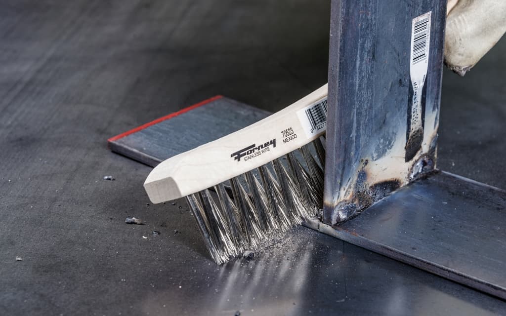
TIG welding isn’t forgiving of dirty material. You must always take the time to remove any dirt, dust, oil, grime, or other contaminants from the surface of the metal before starting.
Some materials will need extra preparation beyond wiping the surface with a solvent.
In particular, mild steel will need the mill scale removed, and aluminum must have the oxide layer brushed off with a stainless steel wire brush.
If you don’t clean the material, your welds will become contaminated and have weld faults, such as porosity.
Even if the weld looks fine, serious faults may lie beneath the surface, making your weld ineffective.
2. Use the Correct Type of Tungsten
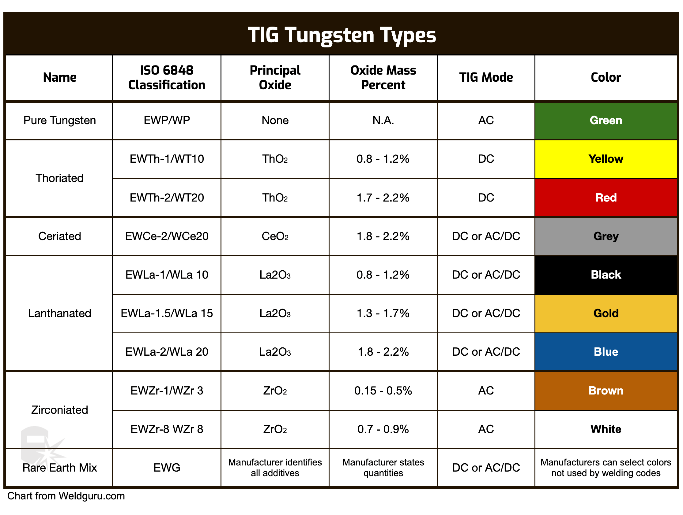
There are many types of tungsten electrodes you can choose from. Selecting the right electrode is one of the most important steps before starting a weld.
© weldguru.com – Image usage rights
A few examples of the more commonly used electrodes are:
Pure Tungsten
Pure tungsten electrodes are 99.5% tungsten. You can identify them by their painted green ends. You’d use them for welding aluminum and magnesium alloys.
Pros
- Good arc stability with AC welding
- Easy to use
- Less expensive
- Good control when using lower current
Cons
- Low current-carrying capacity
- Not suitable for DC welding
Thoriated Tungsten
Thoriated tungsten electrodes have either 1% or 2% thorium oxide. You can identify them by their painted red (2%) or yellow (1%) ends.
These electrodes are the most common you will find in the welding industry. You can use thoriated electrodes on steel, stainless steel, nickel, titanium, and aluminum sometimes.
Pros
- High current-carrying capacity
- Good arc stability
- You can use them in AC or DC welding
- Long electrode life
Cons
- Contain radioactive material, which poses health risks when grinding.
Ceriated Tungsten
Ceriated tungsten has cerium oxide as its alloying element, and you can identify them by its painted grey ends. Ceriated electrodes are versatile and used on mild steel, stainless steel, nickel, and titanium.
Pros
- Good arc starting and stability
- Excellent resistance to weld contamination
- Useful for DC and AC welding
- Longer electrode life when compared to pure tungsten
Cons
- Lower current-carrying capacity compared to thoriated
- May ball up at higher amperages
Lanthanated Tungsten (Gold Tip):
Lanthanated electrodes contain lanthanum oxide. You can identify them by their painted gold ends.
They’re a safer alternative to thoriated electrodes because they have no radioactive elements. You can use these on carbon steel, stainless steel, titanium, nickel, copper, aluminum, and magnesium.
Pros
- Good arc stability
- Longer electrode life
- Good resistance to contamination
- You can use them for DC and AC welding
Cons
- Lower current-carrying capacity compared to thoriated
- Higher initial cost
Zirconiated Tungsten
Zirconiated tungsten electrodes contain zirconium oxide and have a painted white end. You’d use these when you want high-current carrying capacity and resistance to weld contamination.
These electrodes are best for TIG welding aluminum and magnesium alloys.
Pros
- Excellent resistance to contamination
- Good arc stability
- You can use them for AC welding
Cons
- Not good for low-current applications
- Not good for DC welding
Choosing the wrong tungsten will make TIG welding difficult or even impossible, so prioritize your choice of tungsten.
3. Experiment With the Tungsten Profile
© weldguru.com – Image usage rights
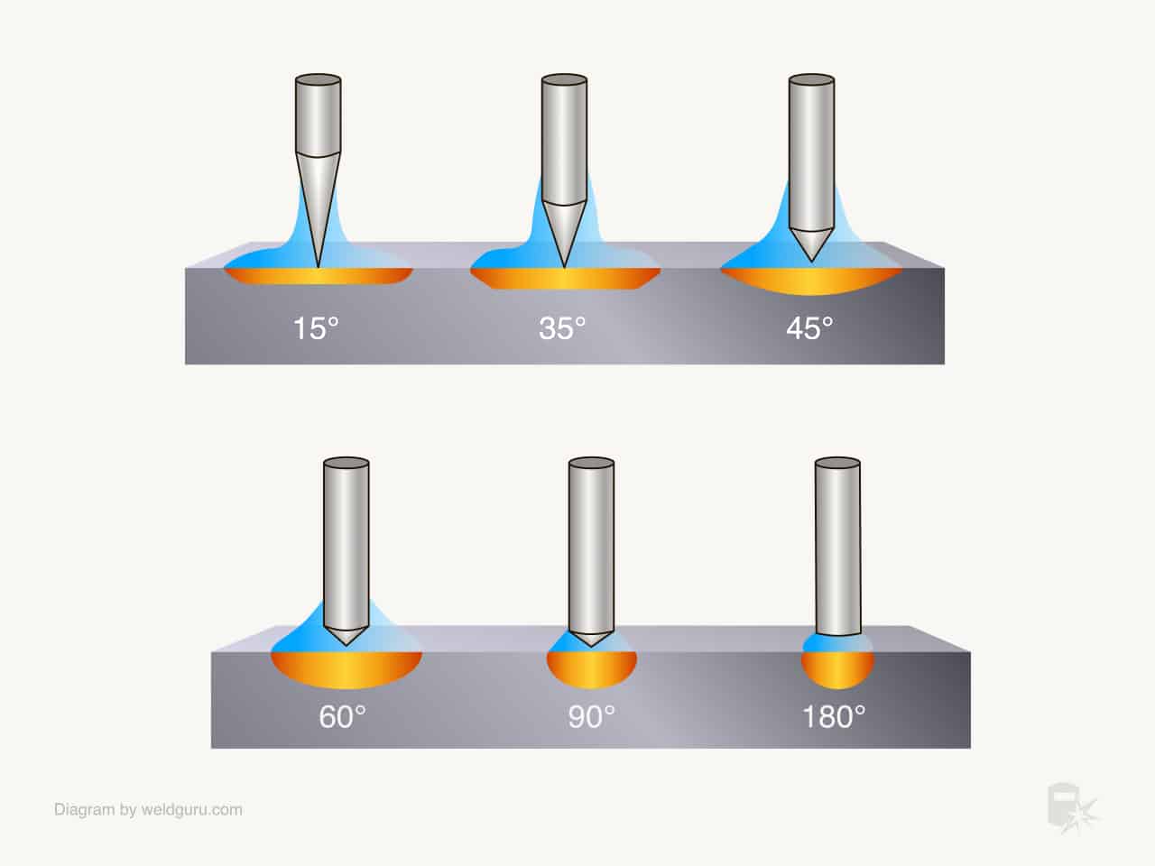
How you shape the end of your tungsten electrode will impact the weld. It’s good to experiment with various profiles to see how each profile affects the weld.
For example, a 15-degree profile will give you less penetration and a wider bead, which is great for thinner materials.
As the angle of the tip profile increases, the bead width will get narrower and the penetration greater.
You’ll use a balled-up tungsten tip for welding aluminum, but some modern machines will allow you to use a pointed tungsten.
If you have a machine that allows you to adjust the AC balance to reduce the DCEP side, you may be able to do this.
Generally speaking, when starting as a TIG welder, you’ll want to keep your tip profile to a 30-60 degree angle, which is suitable for most jobs.
As you get comfortable with TIG welding, you’ll find that adjusting the shape gives you better results.
4. Select the Proper Filler Rod
You’ll use a thin metal rod to add the weld metal into the weld puddle for TIG welding. Selecting the correct filler rod composition is critical to a successful weld.
The types of filler rods vary by the base metals you are welding.
Fortunately, the manufacturers of filler rods provide charts to select the right filler rod for the base metals you’re using.
An advantage of TIG welding is you can take a thin strip of the same metal you’re welding as the filler metal.
You’ll also need to choose the correct diameter of the filler rod. A good rule of thumb is to select a rod less than the thickness of the plate you’re welding.
5. Get Comfortable
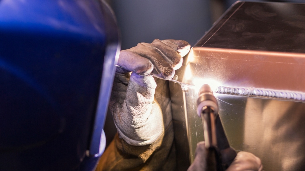
You’ll be using both hands to TIG weld. One hand holds the torch, and the other will dab the filler rod into the weld puddle.
As a result, it isn’t easy to coordinate these movements to form a good weld bead.
Shaking hands will show up in the finished welds as uneven toes and inconsistent travel speeds result in varying weld sizes.
Being comfortable when TIG welding is the best way to have uniform and consistent welds while reducing fatigue.
Here are a few tips to stay comfortable while TIG welding:
- Rest your arms and wrists on something not heating up from the weld.
- Sit down.
- Do not hunch over, and always have good posture.
- Allow the ceramic cup to touch the metal and drag along with the weld so you won’t have to hold it up in free space. Always make sure the tungsten does not touch the weld puddle.
- Use a cup walking technique when pipe welding.
- Use a gas lens, making it easier to control the weld puddle with its laminar gas flow.
6. Limit Your Amperage
When you TIG weld, you must use the lowest possible amperage. Excessive heat input can cause significant problems for some materials.
A few notable examples are:
- Stainless steel will have chromium cooked out of it, reducing the corrosion resistance.
- Aluminum can have the root of the weld joint fall away.
- Too much heat will cause excessive distortion in thinner materials.
- Welds that are too hot will oxidize more rapidly.
Whenever you weld with TIG, you must choose the lowest possible amperage, letting you form a good weld puddle and a sound weld.
7. Set the Right Flow Rate
TIG welding requires an external gas shield to protect the welds from the atmosphere. You’ll use a flow meter on your gas bottle to control the gas flow rate over the weld puddle.
Too little gas flow is a problem because it does not provide enough shielding, but too much flow will cause turbulence in the puddle.
Both extremes will open the weld to contamination, so find the right balance for optimal welding.
A rule of thumb is to set your flow meter between 20 and 35 cubic feet per hour and adjust from there.
8. Don’t Melt the Filler Rod Directly
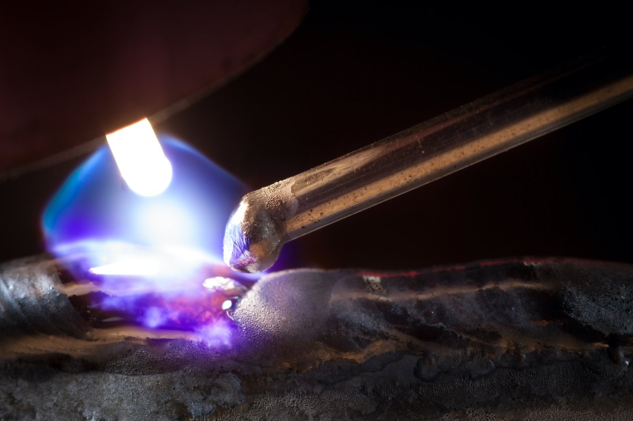
One mistake many TIG welders make is that they’ll melt the filler rod in the welding arc. Doing this isn’t correct.
To add filler metal to the weld puddle, dab the end of the filler rod into the molten puddle, melting it.
If you use the arc to melt the filler rod, you risk accidentally touching it with the tungsten, contaminating it. You will need to resharpen your tungsten if this happens.
9. Pay Attention to the Angles of the Torch
The torch angle is very important for TIG welding because this is how you’ll direct the heat.
If the torch angle is too shallow or steep, the torch won’t direct the heat in a way that gives you the desired results.
The actual angle will vary depending on the situation, but there are some recommended torch angles you can start with.
© weldguru.com – Image usage rights
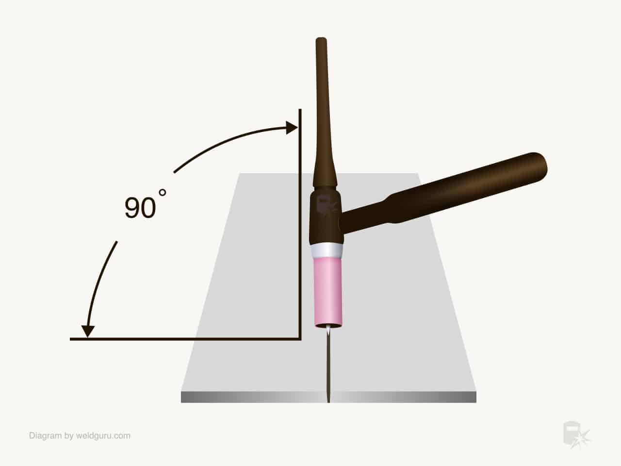
For butt joints, you’ll want your torch to be 90 degrees to the plate.
© weldguru.com – Image usage rights
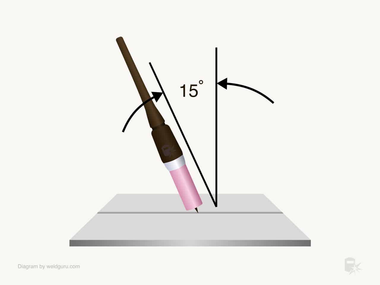
The travel angle is about 15 degrees, so the cup points in the direction of travel. You should adjust the angle depending on the material thickness.
© weldguru.com – Image usage rights
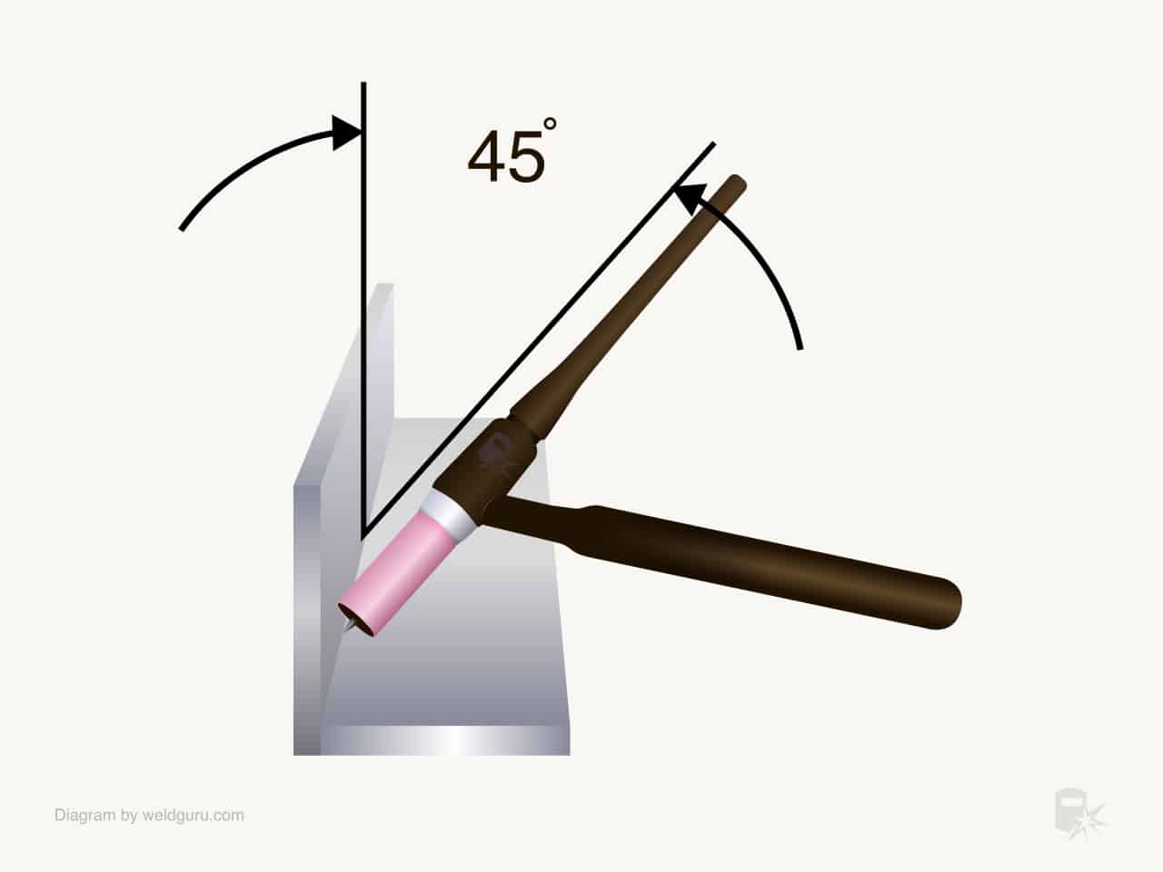
Filet welds use an angle thats 45 degrees to the joint. This angle will allow the metal on either side to melt evenly and give you an equal leg length for the weld.
Sometimes, you’ll adjust this angle to melt one side of the joint more than the other. This method is especially common when one side is a thinner material than the other.
The travel angle for a filet weld is the same as that for the butt weld: around 15 degrees.
These are only suggested torch angles to get you started. As you gain experience in TIG welding, you’ll find a lot of room to adjust your torch angle to suit different scenarios.
10. Move the Torch Smoothly
Every shake and tremor in your hands will manifest themselves in the finished weld. The reason behind this is TIG welding produces the most fluid weld puddle.
This quality makes TIG welding unique from other arc welding processes. Keeping your hands steady is one of the more challenging aspects of TIG welding—one learned through practice and muscle memory.
A few tips can help keep the torch movements smooth:
- Be in a comfortable position.
- Do a “dry run” before welding. I like to run the torch along the weld joint with no arc to see if anything will hang me up or make it tricky to move the torch smoothly.
- If you’re resting your hands on the part, do so lightly to drag them along with the weld.
- Don’t make any sudden changes to travel speed or angle. Keep all your movements gradual and smooth.
11. Maintain a Consistent Travel Speed
The key to consistent weld size is maintaining the right travel speed. If your travel speed varies, the weld’s size will also vary.
The amount of heat imputed into the base metal will also differ, which will cause uneven distortion.
Maintaining travel speed is tricky because your visual perspective is closer to the weld area. You’ll often be much closer to the welding arc when TIG welding than when MIG or stick welding.
This aspect is why it’s easier to determine travel speed in MIG and stick welding; you can see reference points outside the weld area.
One way to combat this is to focus on the width of the weld puddle rather than the speed the torch is traveling at.
As long as you adjust your speed to keep the weld puddle the same width, your travel speed will remain consistent throughout the weld.
12. Don’t Contaminate the Tungsten Tip
© weldguru.com – Image usage rights
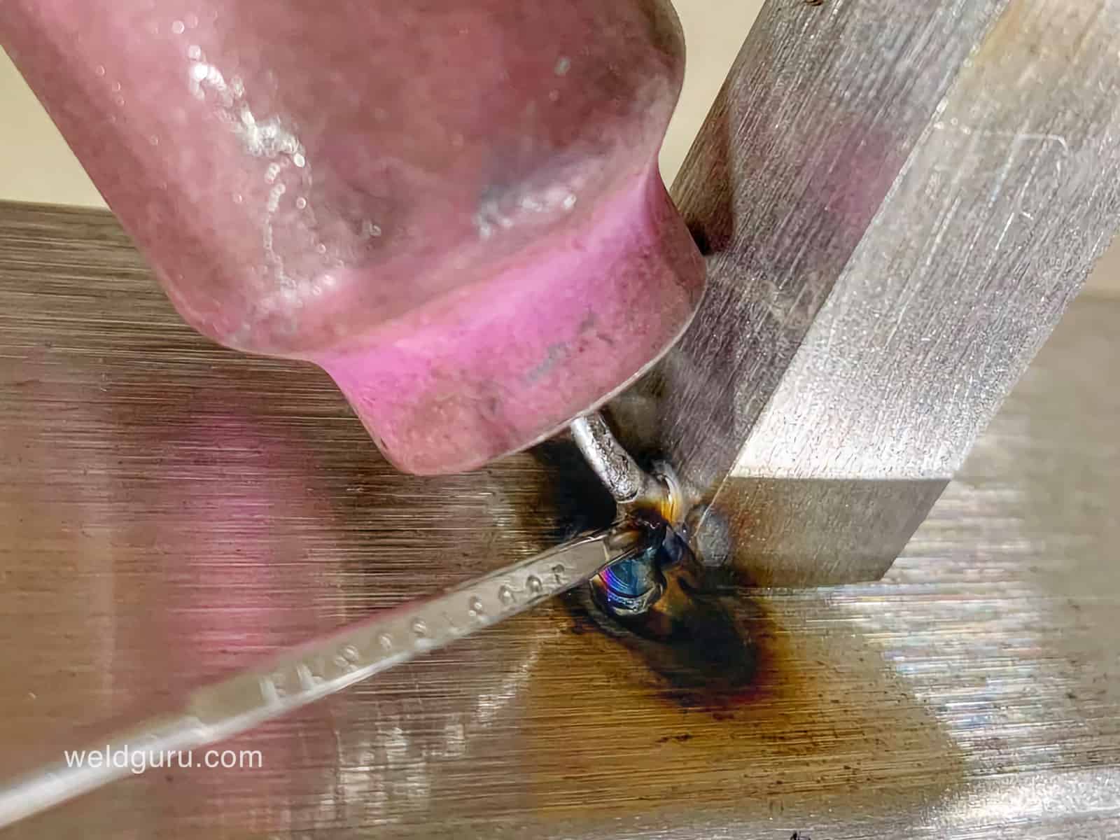
Keeping the tip of your tungsten clean and sharp is essential to good TIG welds. The problem is that it’s easy to accidentally contaminate the tip with the filler, weld puddle, or base metals.
One of the immediate consequences is a drop in arc stability. There is also a good probability that some contaminants will cross the arc into the weld puddle.
The tungsten tip could also break off, leaving a tungsten inclusion inside the weld. When you use excessive amperage, this error can happen.
The best way to avoid contaminating the tip is to keep a consistent arc length and avoid touching the tungsten with the filler rod.
Doing this is very tricky because TIG welding produces the most fluid weld puddle.
You want your tungsten as close to the weld puddle but without touching it to reduce this fluidity as much as possible.
Another thing to consider is never to start an arc without shielding gas. The tungsten needs a protective gas shield, just like the base metals and the weld puddle.
Oxidation will contaminate the surface if the tungsten heats up without a gas shield.
When using scratch start, contaminating the tungsten is much easier, so always use a high-frequency start if possible.
13. Know When to Repair the Tip
© weldguru.com – Image usage rights
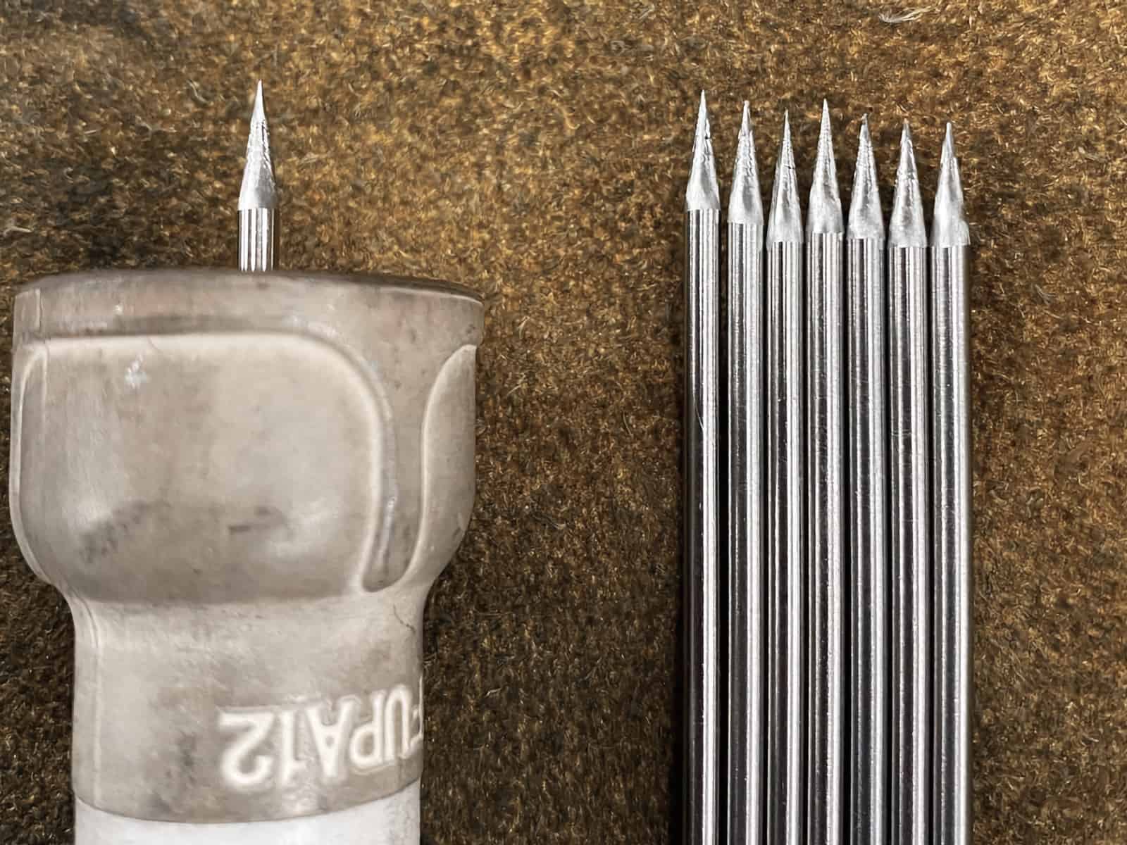
Eventually, the tungsten tip will become contaminated or dull. Then, you’ll re-grind the tip to the appropriate profile.
When I’m TIG welding, I re-profile my tungsten whenever there’s any contamination or when I notice a change in the arc stability.
You shouldn’t be shy about re-profiling the tip. If things aren’t looking right when TIG welding, touch up the tip on a bench grinder. Y
ou’ll often find that the issue will sort itself out. Not doing this literally sets yourself up for disaster.
14. Increase Your Travel Speed With More Amperage
As you increase the welding amperage, you must increase the travel speed to compensate for the increased heat.
You only want to put enough heat into the weld joint to melt the base metal and form a weld puddle.
Any more heat than that will risk blowing through the weld joint or causing too much distortion.
15. Try Wearing Thinner Gloves
Dexterity is critical when TIG welding, but ordinary welding gloves are heavy and thick.
Regular welding gloves protect from heat and sparks, which are less necessary for TIG welding.
Try using welding gloves designed for TIG welding or leather gloves that are thinner than welding gloves. These will give you the manual dexterity that TIG welding requires.
Never use gloves made from anything other than leather. Some thinner gloves you’ll find are rubber or plastic, which will melt when heated.
16. Use a Gas Lens When Welding Stainless Steel
© weldguru.com – Image usage rights
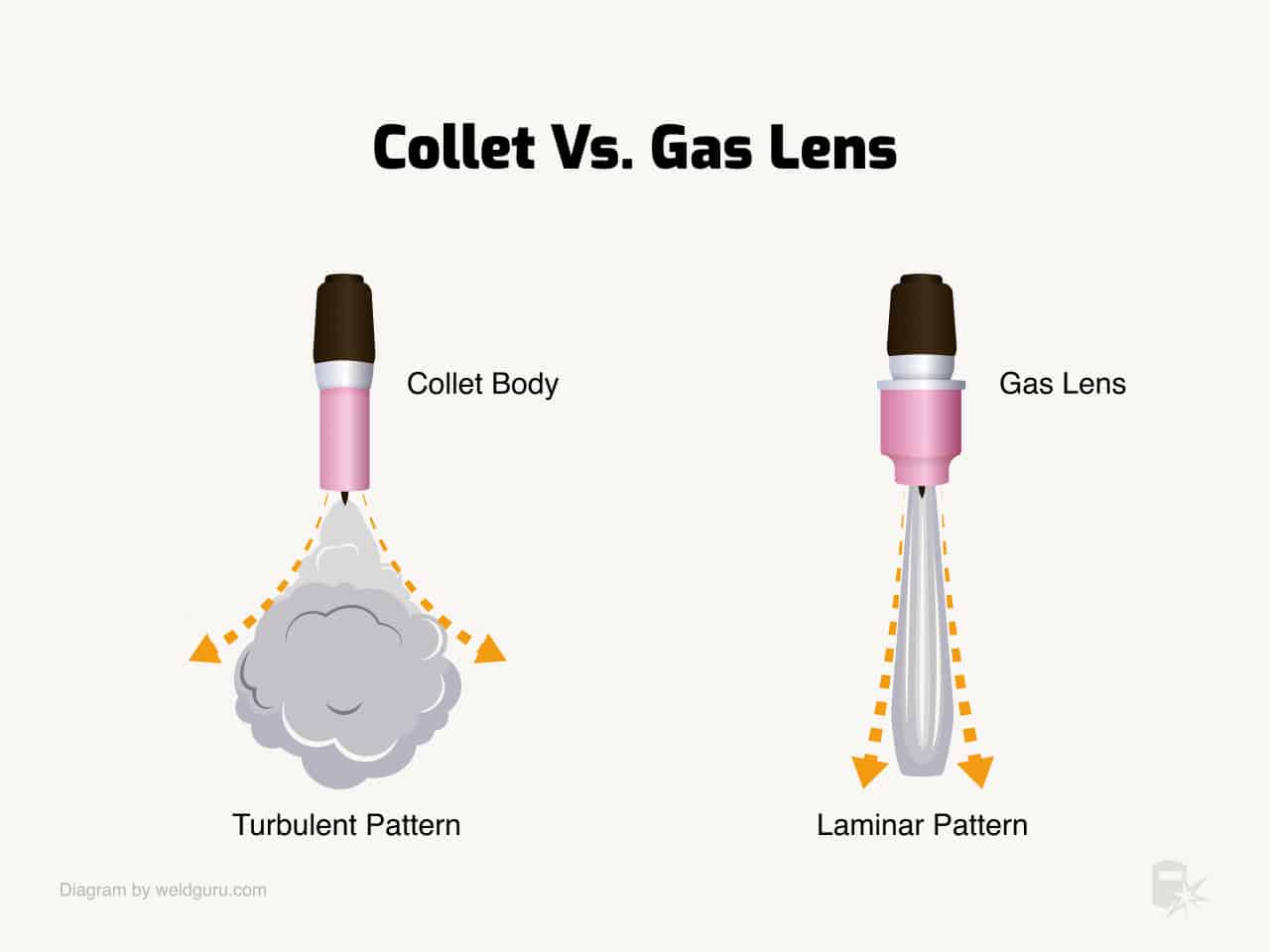
Gas lenses are beneficial when welding on metals susceptible to oxidation, like stainless steel.
A gas lens has several layers of mesh screens through which the shielding gas flows. The result is a more even and predictable shielding gas flow around the tungsten and over the weld puddle.
This laminar flow of gas results in higher-quality welds that look nicer than those made with a regular collet.
Not using a gas lens will still result in sound welds, but the welds done using a gas lens will be far superior in every way.
17. Slowly Reduce Your Arc
As you get to the end of the weld, do not just stop the arc. Instead, slowly let up on the foot pedal to allow the weld puddle to freeze.
Doing so lets the puddle cool at a controlled rate, reducing the likelihood of thermal shock to the weld, which can cause crater cracks.
18. Practice, Practice, and Practice
Since TIG welding requires a lot of manual dexterity and muscle memory, the only way to get good is to practice often. Consistent practice is always going to be the key to success.
I like to have a variety of scrap pieces of metal on hand to practice with in different thicknesses. I also like to do a practice weld before welding something I haven’t welded before.
Wrapping it Up
These are eighteen tips and techniques to elevate your TIG welding game or give you a good start on your TIG welding journey.
TIG welding is a challenging process to get the hang of, but with these tips, you’ll be able to self-correct and set yourself up for success quicker.
