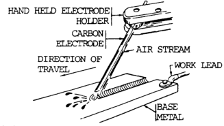
Air carbon arc cutting is an arc cutting process in which metals to be cut are melted by the heat of a carbon arc.
The molten metal is removed by a high velocity blast of compressed air.
The air jet is external to the consumable carbon-graphite electrode. It strikes the molten metal immediately behind the arc.
Required equipment includes an air compressor, welding power source, carbon electrode and a gouging torch.
The air carbon arc process is shown in figure 10-75.
Comparison to Other Processes
Air carbon arc cutting and metal removal differ from plasma arc cutting in that they employ an open (unconstricted) arc, which is independent of the gas jet. The air blast physically removes metal instead of chemically, which is the approach in oxy-fuel cutting processes.
The process is more flexible than oxyfuel processes since it does not require oxidation in order to cut. The most common metals cut with the process includes cast irons, copper alloys and stainless steel. The process is widely used for back gouging, preparing joints, and removing defective weld metal.
Air Carbon Arc Cutting Video
Equipment and Circuit Diagram
The circuit diagram for air carbon arc cutting (CAC) or gouging is shown in figure 10-76. Normally, conventional welding machines with constant current are used. Constant voltage can be used with this process. When using a CV power source, precautions must be taken to operate it within its rated output of current and duty cycle. Alternating current power sources having conventional drooping characteristics can also be used for special applications. AC type carbon electrodes must be used.
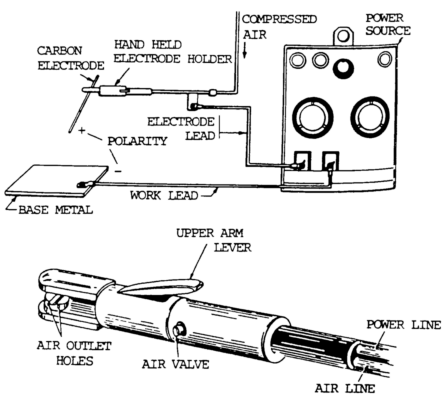
Equipment required is shown by the block diagram. Special heavy duty high current machines have been made specifically for the air carbon arc process. This is because of the extremely high currents used for the large size carbon electrodes.
Electrode Holder
The electrode holder is designed for the air carbon arc process (CAC). The holder includes a small circular grip head which contains the air jets to direct compressed air along the electrode. It also has a groove for gripping the electrode. This head can be rotated to allow different angles of electrode with respect to the holder. A heavy electrical lead and an air supply hose are connected to the holder through a terminal block. A valve is included in the holder for turning the compressed air on and off. Holders are available in several sizes depending on the duty cycle of the work performed, the welding current, and size of carbon electrode used. For extra heavy-duty work, water-cooled holders are used.
Types of Electrodes
Carbon Graphite:
The carbon graphite electrodes are made of a mixture of carbon and graphite plus a binder which is baked to produce a homogeneous structure. Electrodes come in several types.
Plain Uncoated Electrodes:
The plain uncoated electrode is less expensive, carries less current, and starts easier.
Copper-Coated:
The copper-coated electrode provides better electrical conductivity between it and the holder. The copper-coated electrode is better for maintaining the original diameter during operation. It lasts longer and carries higher current. Copper-coated electrodes are of two types
- DC type
- AC type
The composition ratio of the carbon and graphite is slightly different for these two types. The dc type is more common.
The ac type contains special elements to stabilize the arc. It is used for direct current electrode negative when cutting cast irons. AC coated electrodes are made with graphite, carbon and special binder. Rare earth materials are mixed in to ensure stabilization when using alternating current.
For normal use, the electrode is operated with the electrode positive. Electrodes range in diameter from 5/32 to 1 in. (4.0 to 25.4 mm). Electrodes are normally 12 in. (300 mm) long; however, 6 in. (150 mm) electrodes are available Copper-coated electrodes with tapered socket joints are available for automatic operation, and allow continuous operation.
The table below shows the electrode types and the arc current range for different sizes.
| Electrode Type | Electrode Size | Current | ||
|---|---|---|---|---|
| in. | mm | Min | Max | |
| DC (plain) or AC (copper covered) | 5/32 | 4 | 90 | 150 |
| 3/16 | 4.8 | 150 | 200 | |
| 1/4 | 6.4 | 200 | 400 | |
| 5/16 | 7.9 | 250 | 450 | |
| 3/8 | 9.5 | 350 | 600 | |
| 1/2 | 12.7 | 600 | 1000 | |
| 5/8 | 15.9 | 800 | 1200 | |
| 3/4 | 19.1 | 1200 | 1600 | |
| 1 | 25.4 | 1800 | 2200 | |
The polarity of the electrode is positive (reverse polarity).
Note: For DC coppered electrodes current can be increased percent.
Check Manufacturers Directions
Air Pressure
The air pressure is not critical but should range from 80 to 100 psi (552 to 690 kPa). The volume of compressed air required ranges from as low as 5 cu ft per min (2.5 liter per min) up to 50 cu ft per min (24 liter per min) for the largest-size carbon electrodes. A one-horsepower compressor will supply sufficient air for smaller-size electrodes. It will require up to a ten-horsepower compressor when using the largest-size electrodes.
Torch
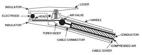
A manual carbon gouging torch is shown above. The torch holds an electrode in a swivel head that has one or multiple air holds. This way the air jet stays aligned with the electrode regardless of the electrode angle to the torch.
If the torch has two heads (air jets on both sides of the electrode) or with a fixed angle between the electrode and the holder, are better for some uses such as large castings (padwashing) or for removing pads.
The torch is cooled by air. If high-current applications are used, then water cooling can be used along with a heavy-duty torch.
Advantages and Major Uses
The air carbon arc cutting process (CAC) is used to cut metal, to gouge out defective metal, to remove old or inferior welds, for root gouging of full penetration welds, and to prepare grooves for welding. Air carbon arc cutting is also used when slightly ragged edges are not objectionable.
The area of the cut is small and, since the metal is melted and removed quickly, the surrounding area does not reach high temperatures. This reduces the tendency towards distortion and cracking.
The air carbon arc cutting (CAC) and gouging process is normally manually operated. The apparatus can be mounted on a travel carriage. This is considered machine cutting or gouging.
Special applications have been made where cylindrical work has been placed on a lathe-like device and rotated under the air carbon arc torch. This is machine or automatic cutting, depending on operator involvement.
Works in All Positions:
The air carbon arc cutting process (CAC) can be used in all positions. It can also be used for gouging in all positions. Use in the overhead position requires a high degree of skill.
Works with Common Metals:
The air carbon arc process can be used for cutting or gouging most of the common metals. Metals include: aluminums, copper, iron, magnesium, and carbon and stainless steels.
The process is not recommended for weld preparation for stainless steel, titanium, zirconium, and other similar metals without subsequent cleaning. This cleaning, usually by grinding, must remove all of the surface carbonized material adjacent to the cut. The process can be used to cut these materials for scrap for remelting.
Process Principles
The procedure schedule for making grooves in steel is shown in the table below…
| Grove Width | Grove Depth | Electrode Dia. | Amps Direct Current | Volts Electrode Postive | Electrode Feed | Travel Speed | |||||
|---|---|---|---|---|---|---|---|---|---|---|---|
| in. | mm | in. | mm | in. | mm | ipm | mm/min. | ipm | mm/min. | ||
| 1/4 | 6.4 | 1/16 | 1.6 | 3/16 | 4.8 | 200 | 43 | 6.2 | 157.7 | 82.0 | 2028.8 |
| 9/32 | 7.1 | 1/8 | 3.2 | 3/16 | 4.8 | 200 | 40 | 6.7 | 170.2 | 38.2 | 970.3 |
| 5/16 | 7.9 | 3/16 | 4.8 | 3/16 | 4.8 | 190 | 42 | 6.7 | 170.2 | 27.2 | 690.9 |
| 5/16 | 7.9 | 1/4 | 6.4 | 3/16 | 4.8 | To make 1/4 in. deep groove, make two 1/8 in. deep passes | |||||
| 5/16 | 7.9 | 3/32 | 2.4 | 1/4 | 6.4 | 270 | 40 | 4.0 | 101.6 | 54.0 | 1371.6 |
| 5/16 | 7.9 | 1/8 | 3.2 | 1/4 | 6.4 | 300 | 42 | 4.0 | 101.6 | 51.0 | 1295.4 |
| 5/16 | 7.9 | 3/16 | 4,8 | 1/4 | 6.4 | 300 | 40 | 6.7 | 170.2 | 38.2 | 970.3 |
| 5/16 | 7.9 | 1/4 | 6.4 | 1/4 | 6.4 | 320 | 42 | 6.2 | 157.4 | 29.5 | 749.3 |
| 5/16 | 7.9 | 3/8 | 9.5 | 1/4 | 6.4 | 320 | 46 | 3.6 | 92.4 | 15.0 | 381.0 |
| 3/8 | 9.5 | 1/8 | 3.2 | 5/16 | 7.9 | 320 | 40 | 3.0 | 76.2 | 65.5 | 1663.7 |
| 3/8 | 9.5 | 3/16 | 4.8 | 5/16 | 7.9 | 400 | 46 | 4.3 | 109.2 | 46.0 | 1168.4 |
| 3/8 | 9.5 | 1/4 | 6.4 | 5/16 | 7.9 | 420 | 42 | 3.8 | 96.5 | 31.2 | 792.5 |
| 3/8 | 9.5 | 1/2 | 12.7 | 5/16 | 7.9 | 540 | 42 | 5.6 | 142.2 | 27.2 | 690.9 |
| 7/16 | 11.1 | 1/8 | 3.2 | 3/8 | 9.5 | 560 | 42 | 4.2 | 106.7 | 82.0 | 2082.8 |
| 7/16 | 11.1 | 1/8 | 3.2 | 3/8 | 9.5 | 560 | 42 | 3.3 | 83.8 | 65.0 | 1651.0 |
| 7/16 | 11.1 | 3/16 | 4.8 | 3/8 | 9.5 | 560 | 42 | 2.5 | 66.0 | 41.0 | 1041.4 |
| 7/16 | 11.1 | 1/4 | 6.4 | 3/8 | 9.5 | 560 | 42 | 3.0 | 76.2 | 29.5 | 749.3 |
| 7/16 | 11.1 | 1/2 | 12.7 | 3/8 | 9.5 | 560 | 42 | 3.2 | 81.3 | 15.0 | 381.0 |
| 7/16 | 11.1 | 11/16 | 17.5 | 3/8 | 9.5 | 560 | 42 | 3.5 | 88.9 | 12.2 | 309.9 |
| 9/16 | 14.3 | 1/8 | 3.2 | 1/2 | 12.7 | 1200 | 45 | 3.0 | 76.2 | 34.0 | 863.6 |
| 9/16 | 14.3 | 1/4 | 6.4 | 1/2 | 12.7 | 1200 | 45 | 3.0 | 76.2 | 22.0 | 558.8 |
| 9/16 | 14.3 | 3/8 | 9.5 | 1/2 | 12.7 | 1200 | 45 | 3.0 | 76.2 | 20.7 | 525.8 |
| 9/16 | 14.3 | 1/2 | 12.7 | 1/2 | 12.7 | 1200 | 45 | 3.0 | 76.2 | 18.5 | 469.9 |
| 9/16 | 14.3 | 5/8 | 15.9 | 1/2 | 12.7 | 1200 | 45 | 3.0 | 76.2 | 15.0 | 381.0 |
| 9/16 | 14.3 | 3/4 | 19.1 | 1/2 | 12.7 | 1200 | 45 | 3.0 | 76.2 | 12.5 | 317.5 |
| 13/16 | 20.6 | 1/8 | 3.2 | 5/8 | 15.9 | 1300 | 42 | 2.5 | 63.5 | 44.5 | 1130.3 |
| 13/16 | 20.6 | 1/4 | 6.4 | 5/8 | 15.9 | 1300 | 42 | 2.5 | 63.5 | 29.5 | 749.3 |
| 13/16 | 20.6 | 3/8 | 9.5 | 5/8 | 15.9 | 1300 | 42 | 2.5 | 63.5 | 20.0 | 508.0 |
| 13/16 | 20.6 | 1/2 | 12.7 | 5/8 | 15.9 | 1300 | 42 | 2.5 | 63.5 | 14.5 | 368.3 |
| 13/16 | 20.6 | 5/8 | 15.9 | 5/8 | 15.9 | 1300 | 42 | 2.5 | 63.5 | 13.0 | 330.2 |
| 13/16 | 20.6 | 3/4 | 19.1 | 5/8 | 15.9 | 1300 | 42 | 2.5 | 63.5 | 11.0 | 279.4 |
| 13/16 | 20.6 | 1 | 25.4 | 5/8 | 15.9 | 1300 | 42 | 2.5 | 63.5 | 10.0 | 254.0 |
- Air Pressure 80 to 100 PSI, (552 to 690 KPa) is recommended for 1/2″ and 5/8″ (13 and 16mm) electrodes.
- A combination of settings and multiple passes may be used for grooves deeper than 3/4″(19mm).
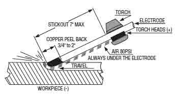
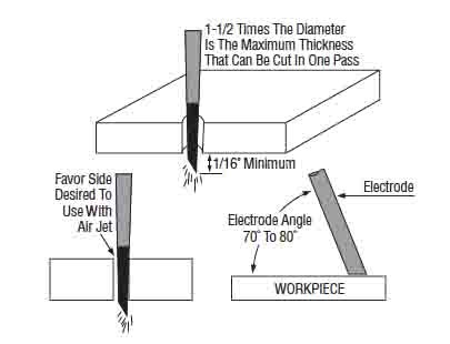
To make a cut or a gouging operation, the cutter strikes an arc and almost immediately starts the air flow.
The electrode is pointed in the direction of travel with a push angle approximately 45° with the axis-of the groove.
The speed of travel, the electrode angle, and the electrode size and current determine the groove depth. Electrode diameter determines the groove width.
The normal safety precautions associated with carbon arc welding and shielded metal arc welding apply to air carbon arc cutting (CAC) and gouging. However, two other precautions must be observed.
First, the air blast will cause the molten metal to travel a very long distance. Metal deflection plates should be placed in front of the gouging operation. All combustible materials should be moved away from the work area. At high-current levels, the mass of molten metal removed is quite large and will become a fire hazard if not properly contained.
The second factor is the high noise level. At high currents with high air pressure, a very loud noise occurs. Ear protection, ear muffs or earplugs should be worn by the arc cutter.
Hi looking for a bit advice for a works problem. Inside the torch there’s a nut that allows it to rotate this has become very stiff to turn resulting in the cable having to be changed. Its happened 3 times over the last 4 weeks and the engineering department dont seem interested in finding out why. Any advice you could give would greatly be appreciated.
Kindest regards
Martin