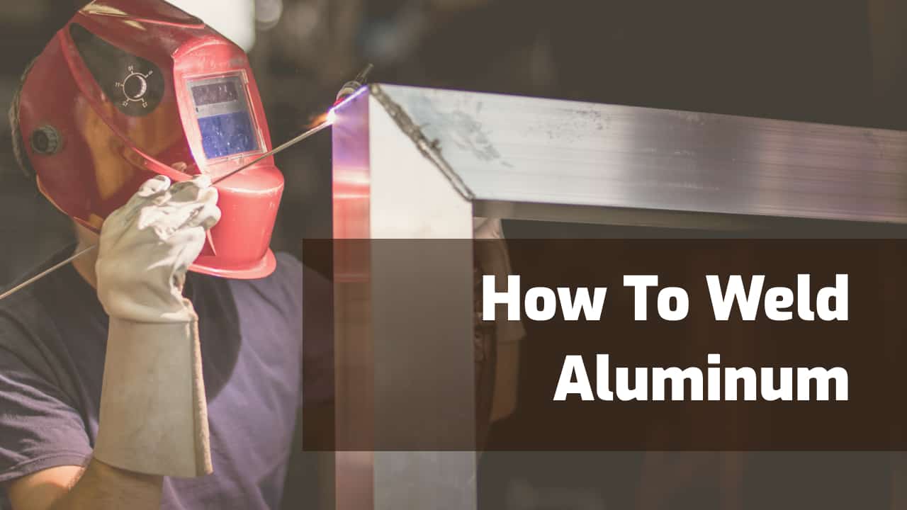
Aluminum is a lightweight, strong, versatile material widely used in marine, aerospace, and automotive applications.
You may consider aluminum welding complicated and too advanced for your skills, but the good news is that aluminum welding is well within your reach with a bit of knowledge and some practice.
FAQs About Welding Aluminum
Before diving into the how, let’s clear up some commonly asked questions about welding aluminum.
Can You Weld Aluminum?
Yes, you can weld aluminum, usually with TIG welding (GTAW), but you can also do it with other arc welding processes like MIG (GMAW). Unlike steel, welding aluminum needs specialized equipment and skill due to aluminum’s unique properties, like high thermal conductivity.
Is Aluminum Difficult To Weld?
Compared to steel or stainless steel, aluminum has several attributes that make it more challenging to weld.
If you’ve spent most of your time welding steel and stainless steel, aluminum will be a much different beast to tame.
- Aluminum has high thermal conductivity and a low melting point. This attribute can lead to distortion, burn-through, and cracking of welds.
- Unlike steel, aluminum goes from solid to molten without changing color first. So this means that the puddle appears without warning, and if you’re not ready for it, you could burn through the material.
- Aluminum has a protective oxide on its surface that protects the metal. The problem with this oxide coating is that it takes much more heat to melt than the metal underneath. For example, aluminum melts around 1200 degrees Fahrenheit, but the oxide melts at 3700 degrees.
- Contamination is a primary concern when welding aluminum. Unlike steel, aluminum isn’t forgiving of contaminants at all in the weld area. As a result, you must clean aluminum before welding, or you’ll get porosity, cracking, or other weld defects. Rule of thumb: You weld mild steel clean, stainless steel even cleaner, and aluminum the cleanest to avoid welding defects.
Read more: Is It Possible to Weld Aluminum to Steel?
What Type of Welder Is Used for Aluminum?
TIG and MIG are the most popular and effective methods for welding aluminum.
Most people use TIG welding because it gives clean, high-quality welds and is easier to see the weld pool.
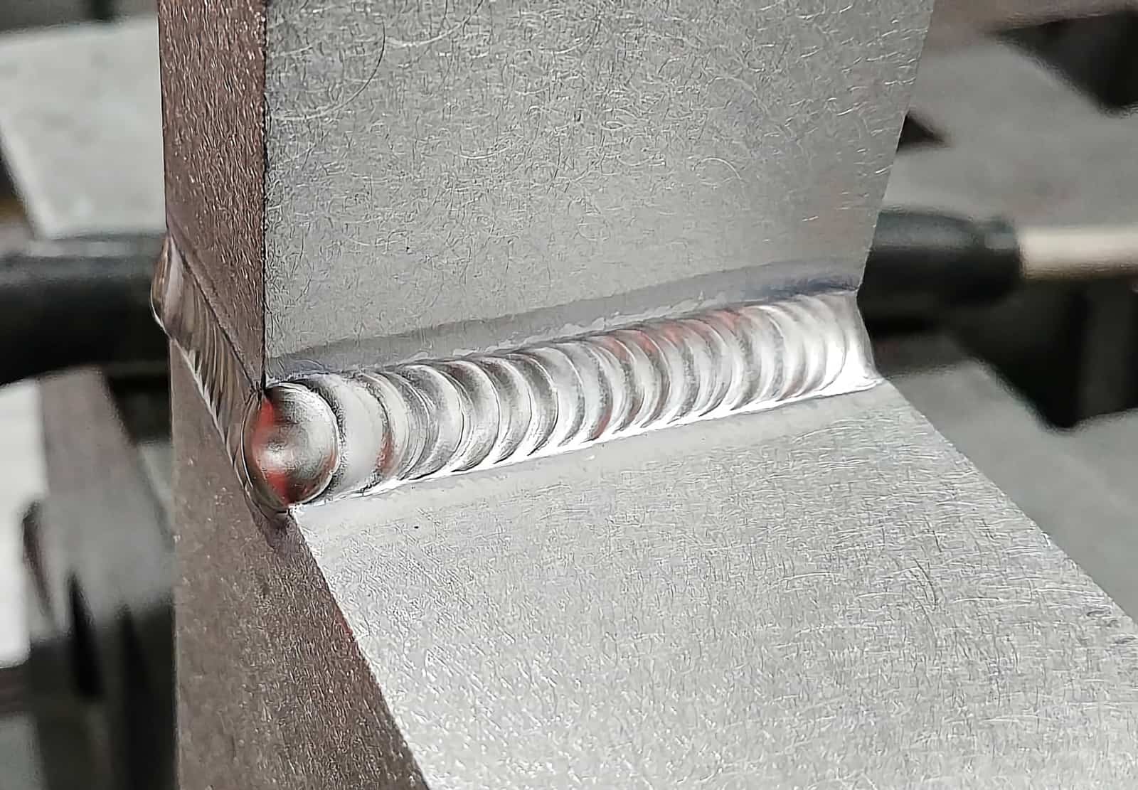
© weldguru.com – Image usage rights
TIG welding also allows you to control all the aspects of the welding during the weld. This is important when the aluminum starts heating up.
With TIG welding, you don’t need as much heat as you do at the start of the weld start because the weld bead goes along the material.
MIG welding is also very effective, but the welds aren’t as clean or high quality. You’d use MIG for thicker aluminum plates where your TIG machine may not have enough power or be as efficient.
When production trumps quality, you might use MIG because it’s faster and requires less skill.
TIG Welders
In most shops I’ve worked at, TIG was always the first choice for welding aluminum. Once you’re comfortable with the process, it’ll always be the best for producing the highest quality welds.
With TIG welding, you’ve got a lot of control over all aspects of the welding. You can adjust the heat according to how the metal is heating up during the weld, which helps to prevent burn-through.
TIG welding is slower because you’re dabbing the filler metal into the weld puddle. The slow speed allows you to make nice-looking welds that often need minimal post-weld cleanup.
Pros
- You get high-quality, cleaner welds than you would with MIG welding.
- The process is effective on many thicknesses of material depending on the machines amperage.
- AC TIG eliminates the oxide layer, providing clear visibility of the weld pool.
- TIG works well with thinner aluminum sheets.
Cons
- TIG welding is slower than MIG welding.
- It will take some time, as this is the hardest process to learn.
- Equipment is more expensive than MIG welders.
MIG Welders
MIG welding is faster, easier to learn, and cheaper than TIG welding, so it remains a popular choice for welding aluminum.
MIG welding machines use a specialized welding gun and cable called a push/pull gun. These welding guns have feed rolls that pull the wire, which the welding machine’s wire feeder pushes through the liner.
You need to use this style of welding gun because the aluminum wire is so soft it’ll bend, kink, or bind inside the liner. The pulling action of the gun’s wire feed prevents this from happening.
For shops that don’t MIG weld a lot of aluminum or don’t want to spend too much money on equipment, there’s also the option of spool guns. Spool guns are welding guns with wire and feed rolls contained in one package.
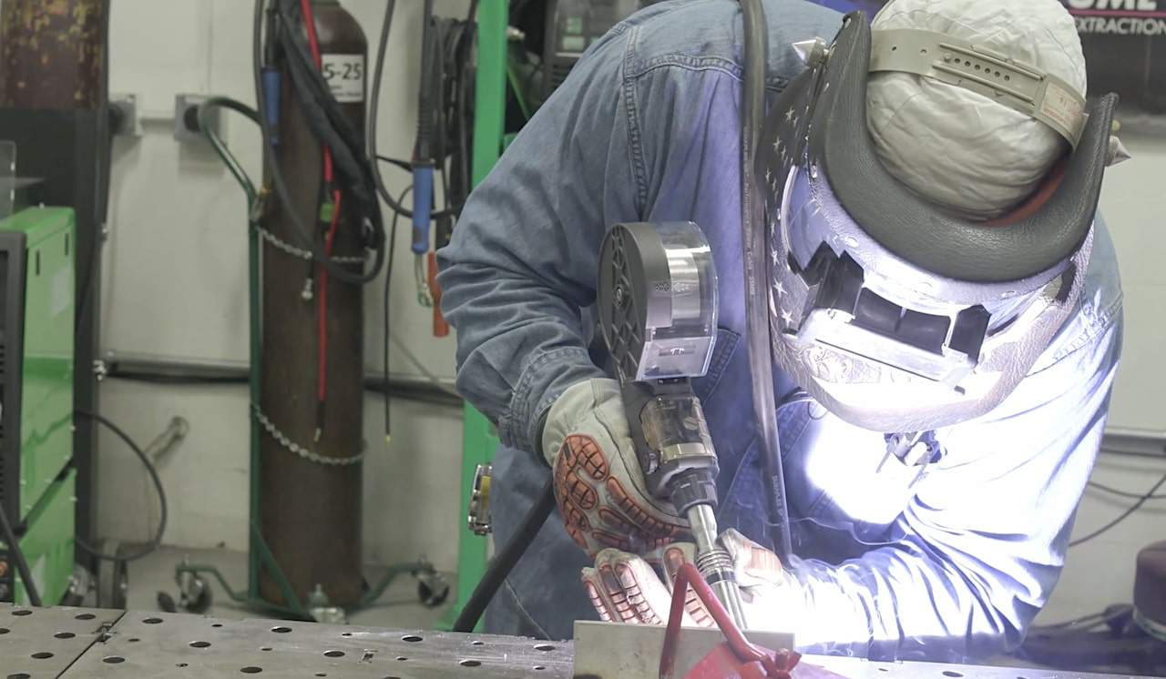
Another aspect of MIG welding aluminum that’s worth mentioning is pulse MIG. Using pulse MIG can produce high-quality welds, as it’s easier to control the weld puddle.
The pulsing action allows for much greater control of the heat put into the metal. Pulse MIG will help prevent distortion and burn-through while making a nice-looking weld.
There are two instances where I would choose MIG over TIG for aluminum welding. The first is when the production speed is more critical than the weld looking nice or being high quality. The second is when the material is too thick for the shop TIG welding machine to handle.
Pros
- Faster than TIG
- Effective for welding thicker materials
- Easier for beginners compared to TIG
Cons
- Welds aren’t as high quality
- Welds don’t look as nice as TIG welds
- Not so good with thinner aluminum sheets
What about Stick (SMAW) and Flux Core (FCAW) Welding?
Stick-welding aluminum is possible, but achieving a reasonable result is difficult. You’d only use a stick welder to weld aluminum for quick repairs in the field.
The appearance and quality of the finished weld aren’t good compared to MIG or TIG.
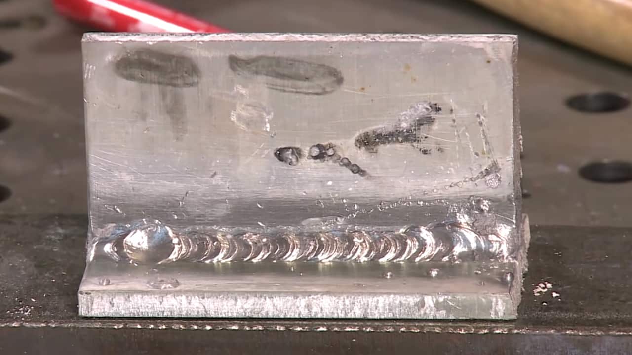
Aluminum stick welding will present you with several challenges to overcome:
- You’ll use more amperage and need to weld a lot faster than you would for steel because of the high thermal conductivity of aluminum.
- Aluminum stick welding electrodes are very sensitive to moisture. You’ll have to take a lot of care in where and how you store them. Often, you’ll need to store them in a rod oven on low heat to keep them dry.
- As you weld the aluminum joint, you’ll need to keep the arc length short, which can cause the electrode to stick to the joint during welding.
- Once the weld is complete, you’ll have a lot of spatter and slag to clean off. The slag especially will be quite difficult to remove.
Read: Can you stick weld aluminum?
I’ve welded aluminum with a stick welder only a handful of times. It was frustrating, gave poor results, and made me never want to do it again.
As for flux core welding (FCAW) of aluminum, the AWS doesn’t list any flux core wire for aluminum. This absence means that aluminum flux-core welding wire doesn’t exist.
You may find aluminum flux-core welding wire online, but these wires aren’t certified by the AWS and are often soldering or brazing wires.
Preparing To Weld Aluminum
One piece of advice I’ve received about welding aluminum that you should also take to heart is that preparing the base metals is critical.
There’s no circumstance where you should skip or cut corners on the cleaning and preparation of aluminum.
Cleaning Aluminum
Aluminum must be spotless before you even think about welding it. So remove the oxide, and wipe the surface clear of dirt, grime, or other contaminants before you even tack the pieces together.
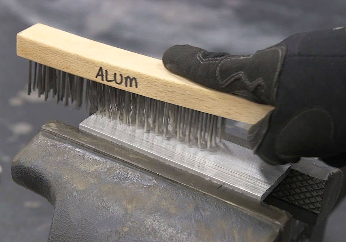
When removing the oxide, don’t use a grinder. Angle grinders often cause the oxide to fold into the base metal rather than remove it.
Instead, use a stainless steel wire brush to scrub away the aluminum oxide. If you use a wire wheel on an angle grinder, use one with soft stainless steel bristles, not one with hard and twisted bristles.
Have these tools labeled for aluminum only so you don’t introduce contaminants from other steels.
When wiping any other contaminants away, avoid using any chlorinated solvents. They may produce dangerous gasses because they react to the electric arc and turn into gasses like phosgene, which could be deadly.
Choosing the right filler material
The choice of filler metal is a critical consideration and depends on what grade of aluminum you’re welding.
You need to match the filler metal with the base metal and consider the properties you want your weld to have.
For TIG welding, the filler metal will come in long rods of various diameters that you dab into the weld puddle. The filler metal for MIG comes in spools of aluminum wire in various diameters.
There are almost as many filler metals as there are grades of aluminum, and you should always research before choosing one for your next project. For most aluminum welding that you’ll be doing, there are two main types of filler metals for both TIG and MIG.
- 4043 – You’d often use 4043 on 6000 series aluminum, but you can also use it on 2000 or 3000 series. 4043 has silicon added, which makes the puddle more fluid, improving the wetting action but making it harder to control. The finished welds are bright, good-looking and resistant to cracking. When compared to 5356, 4043 has better penetration and a lower cost.
See a TIG 4043 filler example here and a MIG 4043 wire here. - 5356 – One of the most common filler metals, designed for 5000 and 6000 series aluminum. 5356 isn’t suitable for welding on casings, whereas 4043 is. One major limitation of 5356 is that it’s not good for service temperatures over 150 degrees Fahrenheit due to the possibility of stress corrosion. But 5356 is the better option for parts that get anodized than 4043. 5356 also has a higher shear strength and tensile strength than 4043.
See a TIG 5356 filler example here and a MIG 5356 wire here.
Choosing the right gas
Your choice of shielding gas is critical in setting up either a MIG or TIG machine for welding aluminum. Shielding gas protects the weld from the atmosphere and influences the arc, heat transfer, and penetration.
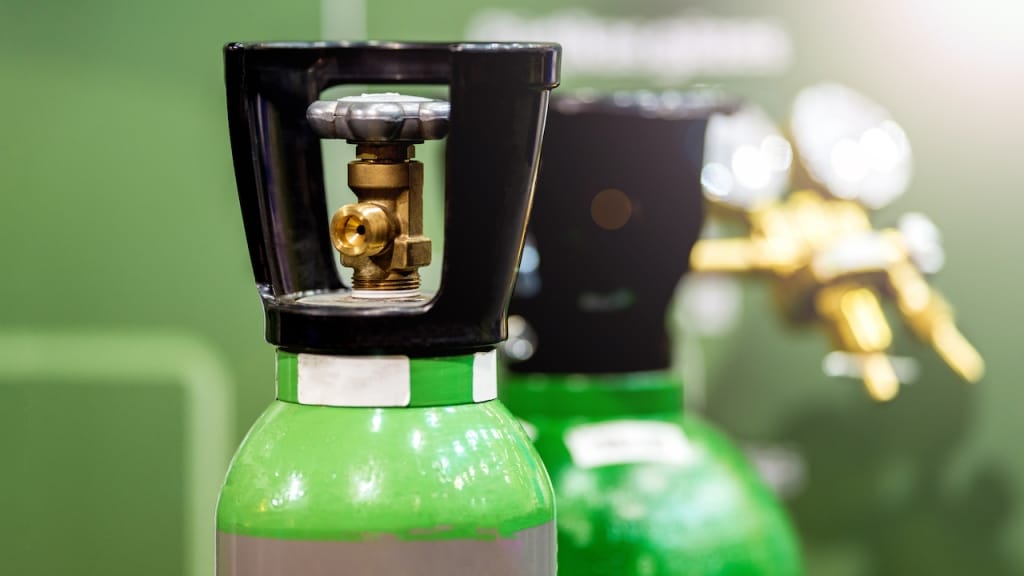
The most common gas for MIG welding aluminum is 100% argon, which performs very well in most instances. Argon is also the least expensive option for aluminum shielding gas.
You should consider using a helium/argon mix in certain situations. Adding helium increases the arc voltage, widens the fusion area in the weld zone, reduces the possibility of gas entrapment.
Generally, you’d choose helium for thicker materials and higher welding speeds.
The problem is that helium is more expensive than argon, increasing costs. Welds made with a helium mix will also need more post-weld cleaning.
You can also use 100% argon for TIG welding aluminum, but like MIG welding, you may consider using helium or an argon/helium mix.
A helium/argon mix is good for increasing travel speed during TIG welding but not in ratios greater than 25% helium. When the mixture of helium gets too great, the AC arc can be unstable.
You’d use high ratios of helium or pure helium for TIG welding with DC electrode negative (DCEN). You’ll get fast welding speeds and excellent penetration, suitable for thicker plates.
Setting up Your Welding Machine
Setting up the aluminum welding machine is very different from setting it up for mild steel or stainless.
Many unique considerations are critical for your success.
TIG
- Ball the electrode with a clean piece of copper or scrap of aluminum.
- Set the welding machine to AC high frequency.
- Set the amperage. A good rule of thumb is one amp per 0.001″ of material thickness.
- Adjust the output frequency—150-250 hz for thin materials and 80-120 hz for thicker materials.
MIG
- Clean the wire feeder feed rolls.
- If using a regular MIG welding gun, replace the liner and clean the nozzle. Use only new contact tips, not ones used on steel.
- Clean the gun’s feed rolls if you use a push/pull gun.
- Use feed rolls designed for aluminum welding. They’ll be U-shaped rather than V-shaped.
- Adjust the tension of the feed rolls to avoid squishing the wire.
- If you use a spool gun, attach it to the machine and confirm it’s operating.
- Set the voltage and wire speed.
9 Tips To Weld Aluminum Successfully
1. Preheat the metal
There’ll be many times when you’ll find it difficult to get your weld going. Using thicker aluminum is especially difficult because the weldment you’re working on will suck the heat out of the weld area.
To avoid this, you can preheat the part which causes slower cooling. Preheating will also help reduce the part’s cracking and distortion because heat will draw out of the weld area at a controlled rate.
Don’t overdo it with the preheating, as you will significantly degrade aluminum’s mechanical properties. Each grade of aluminum has a maximum preheating temperature.
2. Control the Heat
Aluminum has a higher thermal conductivity than steel, so you’ll use twice as much heat to get a weld puddle than steel.
With TIG welding, you’ll control the heat input utilizing the foot pedal, but with MIG, you’ll need to adjust the gun angle and travel speed.
If you’ve got a pulse MIG machine, I suggest always using it for aluminum MIG welding to control the heat input.
3. Use a faster travel speed
Since aluminum has such high thermal conductivity, you must weld hot and fast. Your travel speed will be faster than that of steel welding.
4. Use Proper Torch Angles
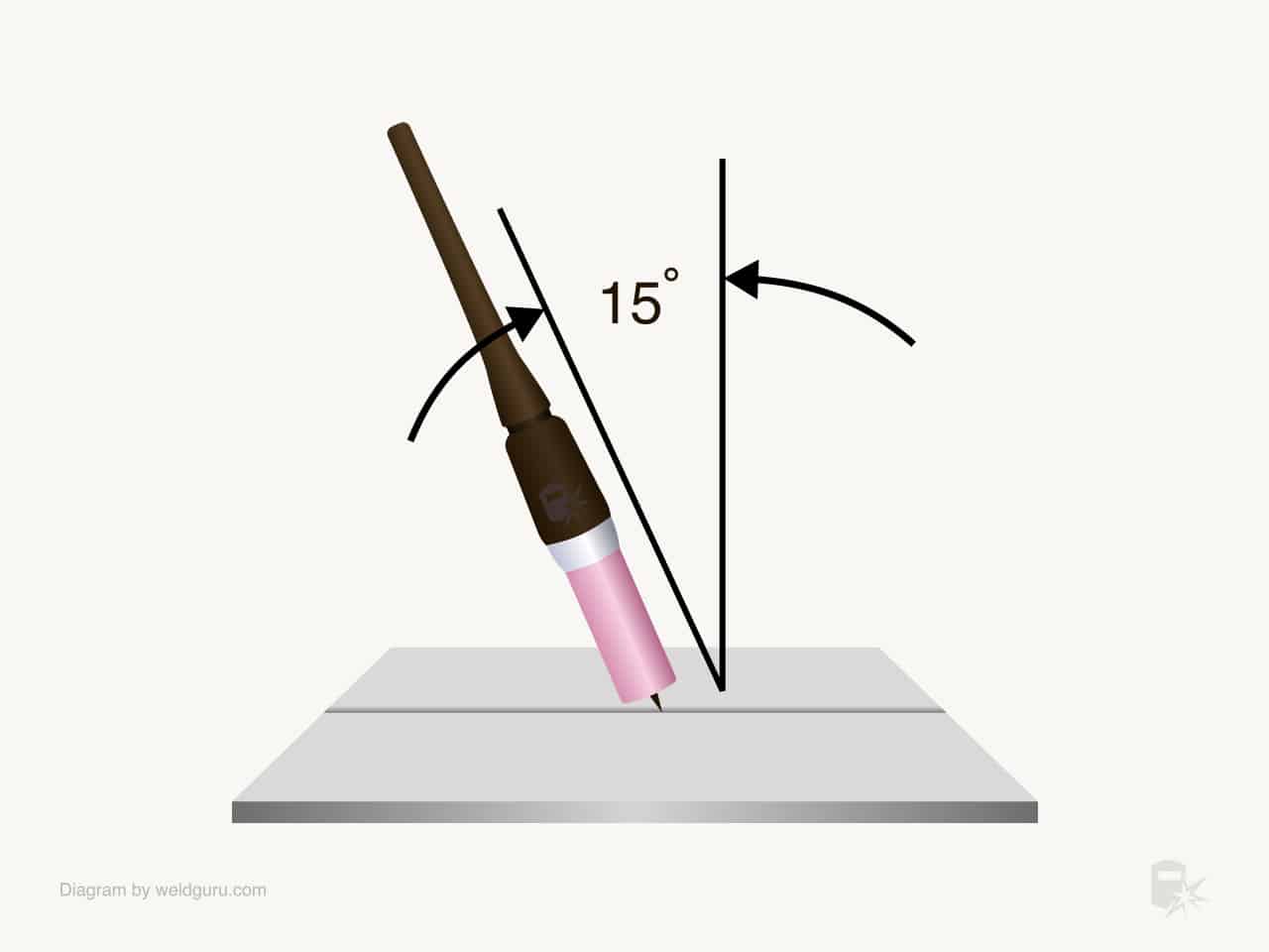
You want a torch/gun angle around 15 degrees for both TIG and MIG. It may be tempting to widen this to see your weld, but if you widen the angle too much, you’ll end up “shooting your arc down the park.”
For TIG welding, this will cause the filler metal to melt before it even reaches the puddle.
© weldguru.com – Image usage rights
5. Use Alternating Current (AC) for TIG
Unless you’re welding with pure helium gas, you’ll be TIG welding with high-frequency AC.
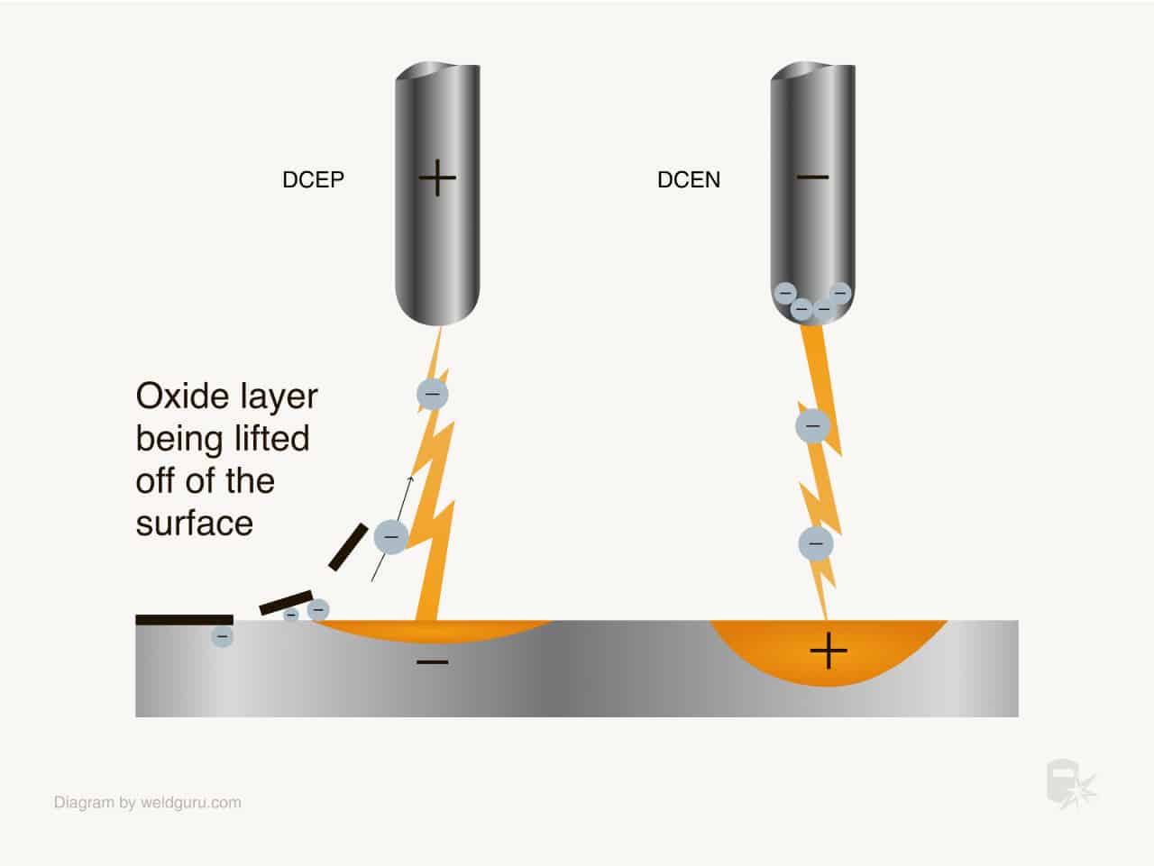
Using AC polarity facilitates a cleaning process that effectively eliminates the oxide layer on aluminum, which provides clear visibility of the weld pool.
Looking closely, you will see a sandblasting effect removing that oxide layer.
© weldguru.com – Image usage rights
6. Use the correct tungsten for TIG
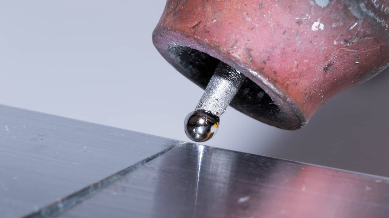
You’ll use pure tungsten electrodes for TIG welding aluminum. These electrodes need to be “balled” before use.
To ball the tip, adjust the AC balance to maximum on DCEP and minimum on DCEN. Grind a slight bevel on the unpainted end of the tungsten.
Don’t grind the painted end to identify it as pure tungsten. Start the arc on a scrap piece of copper or aluminum and watch the end of the electrode form a ball.
The ball should never be more than 1.5 times the electrode diameter.
7. Use a spool gun for MIG
A spool gun is a great way to MIG weld aluminum without changing the MIG welding machine from steel.
All you need to do is connect the spool gun to the proper locations on the machine, and you’re ready to weld aluminum.
I have put in many hours on a spool gun, and they’re a great option for the occasional aluminum welding job.
8. Using a Push Technique For MIG
© weldguru.com – Image usage rights
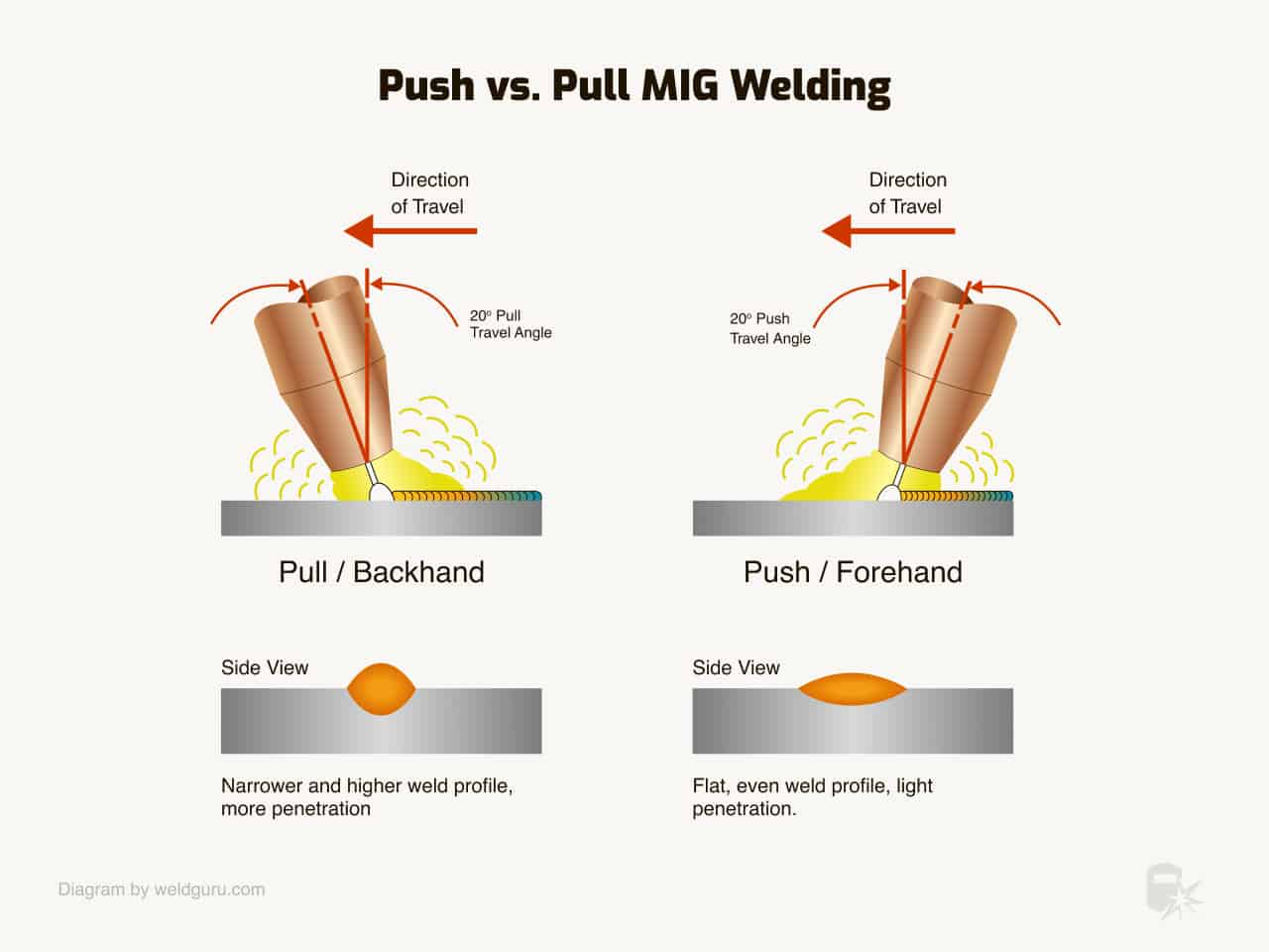
For aluminum MIG welding, you should always use the push technique. A pull technique leaves you with less gas coverage, leading to porosity and dirty welds with aluminum.
9. End the weld correctly
Leaving a crater not only looks terrible but holds the potential to form cracks and cause the entire weld to fail. I’ve seen it happen several times when a small crater crack will spread and split the weld in two.
When TIG welding, lighten up on the foot pedal as you approach the end of the weld. Keep adding the filler metal as you release the pedal and build up the end of the weld to match the height of the rest of it.
When using MIG, I’ve found the best way to finish the weld is to backstep the end. To do this, stop the weld an inch or two from the end of the joint.
Then weld from the end of the joint and burn into the crater of your original weld, going about a half inch into the weld.
Common Problems Welding Aluminum & How To Avoid Them
Aluminum welding has a lot of potential issues that’ll arise while you’re welding. Cracking, porosity, burn-through, and oxidation are the main problems you’ll face.
Once you understand these issues, you can take measures to prevent them from becoming serious problems.
Cracks
There are many reasons that your aluminum weld may crack. One of the most common causes of cracking in an aluminum weld is the difference in melting points of the alloying elements.
When these elements solidify at different times, they can form brittle compounds that may crack.
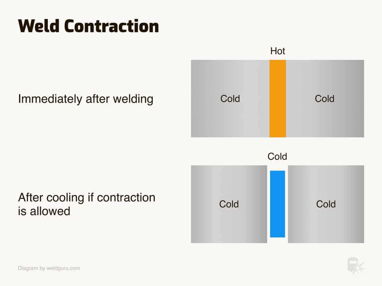
The aluminum’s high thermal conductivity is another reason your weld could crack. When the cooler parts of the weldment pull heat away from the weld zone too fast, it can cause the weld metal to crack as it cools.
© weldguru.com – Image usage rights
Pre and post-heating the weldment is a great way to reduce cracking in the weld area. If you can maintain a slow and gradual cooling of the entire part, there’ll be less chance of cracks forming.
Proper fit-up is also vital in preventing cracking. You need to think about how the thermal conductivity of aluminum will affect the weld joint.
If you don’t allow for some expansion and contraction space, the stress will go into the weld itself, which can cause cracks to form.
Porosity
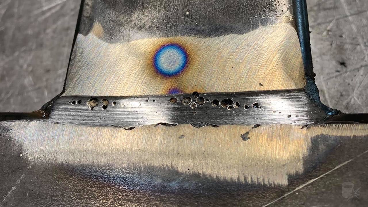
Porosity refers to small gas pockets or holes inside of your weld that make it look ugly and mean that your weld isn’t sound.
There are many possible causes of porosity, and the good news is that most of them are preventable.
© weldguru.com – Image usage rights
The two most common in my experience are cleanliness and poor shielding gas coverage.
If the base metals are dirty, contaminants will enter the weld puddle and the weld itself. Always take your time when preparing and cleaning the weld joint before you begin fabrication.
Aluminum is a porous metal. Fixing an old aluminum welding project, such as a fuel tank, may take grinding out several welts to remove all the impurities and finally get a sound weld.
Poor shielding gas coverage is also a major cause of porosity due to improper gas flow rate, holding the nozzle too far from the weld joint, improper torch angle, or wind. If the shielding gas cannot do its job, the weld will be full of porosity.
Keep in mind how the flow of the shielding gas is covering the weld area. You must also maintain the correct torch angle and stay aware of any wind or drafts in the work area.
Burn through
The high thermal conductivity of aluminum means you need a lot more heat to get the metal to melt enough to form the weld puddle.
When the heat gets too high, the metal can melt so much that it falls away, causing a hole in the material.
But burn-through doesn’t always need to be a hole through the plate. It can also appear as melted or bubbled material on the backside of the joint.
Controlling the heat input is the best way to prevent this from happening to you. By adjusting the voltage, wire speed, and rate of travel, you can keep the heat from getting out of control.
Oxidation
As you weld aluminum, it’ll react with the oxygen in the air to form aluminum oxide. The shielding gas will protect the weld from this process, but if this shield is ineffective, you may notice that your welds are not clean and shiny.
If you see black soot on your welds, that’s not aluminum oxide but magnesium oxide. This happens when magnesium is present in filler or base metal.
The best way to prevent oxidation is to maintain good shielding gas coverage and always clean the aluminum before welding.
Wrapping It Up
Aluminum is such a useful and versatile material, and it’s worth your time and effort to learn the ins and outs of welding it.
At first, it’ll seem tricky and even frustrating, but with practice, you’ll master its welding in less time than you think.
