The groove weld symbol is a common weld symbol every welder encounters regularly.
According to the AWS, a groove weld is a weld in a groove on a surface, between surfaces, between edges, or between an edge or a surface.
A groove is a channel or an opening between two joint members containing the weld metal. You’ll make the groove by removing material from the weld joint to a specified size and angle.
This guide aims to help you understand bevel and V groove weld symbols and the joint preparations they call for.
While there are many different types of groove weld symbols beyond these, the groove and V groove symbols are the ones you’ll see the most.
Plate Preparation: Which Plates Get the Bevel?
The common mistake in preparing groove welds is beveling the wrong side of the joint. Also, I encounter a lot of welders who need help understanding what size or angle the joint needs to have.
The solution to this problem is a good understanding of a groove weld symbol’s structure because all the information you need is there.
Bevel Groove Plate Preparation
When you see a single bevel groove weld symbol, you must determine which plate will get the weld prep. Fortunately, the welding symbol makes this information clear and easy to understand.
© weldguru.com – Image usage rights
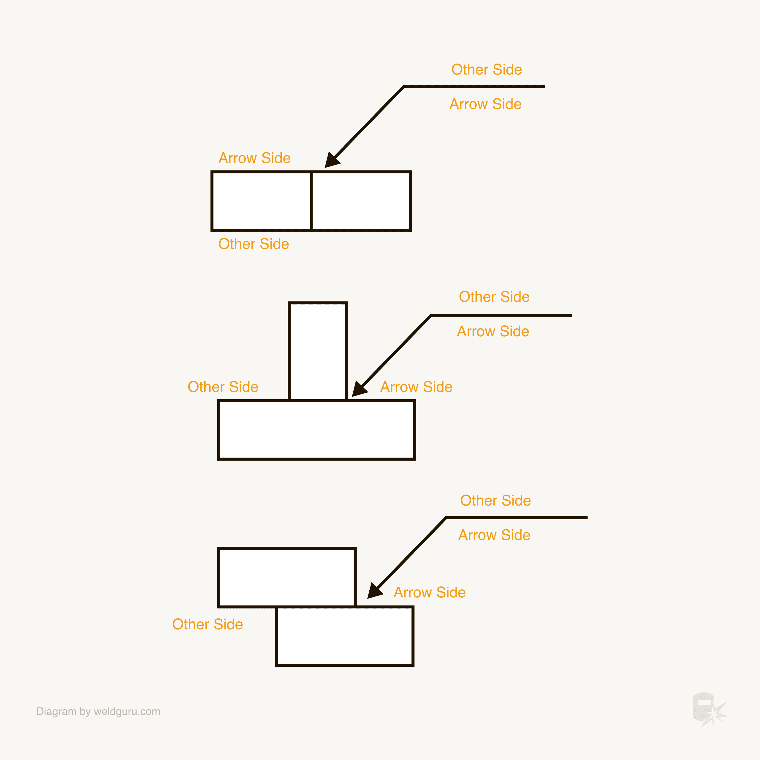
The first key to understanding where to place the weld prep is understanding the welding symbol’s structure.
The line on which you see the weld symbol is the reference line. This line has an arrow side and the other side. The arrow side is on the lower side of the line, while the other side is on the upper side of the line.
Depending on which side of the line the weld symbol is on, that tells you which side of the joint gets the weld and the weld prep.
The arrow side is the side of the joint that the arrow is pointing to. This means that if you see an arrow side groove weld symbol, you’ll be beveling and welding the side of the joint to which the arrow is pointing.
In a single groove weld, you’ll need to know which side of the joint gets the bevel and which plate gets beveled.
© weldguru.com – Image usage rights
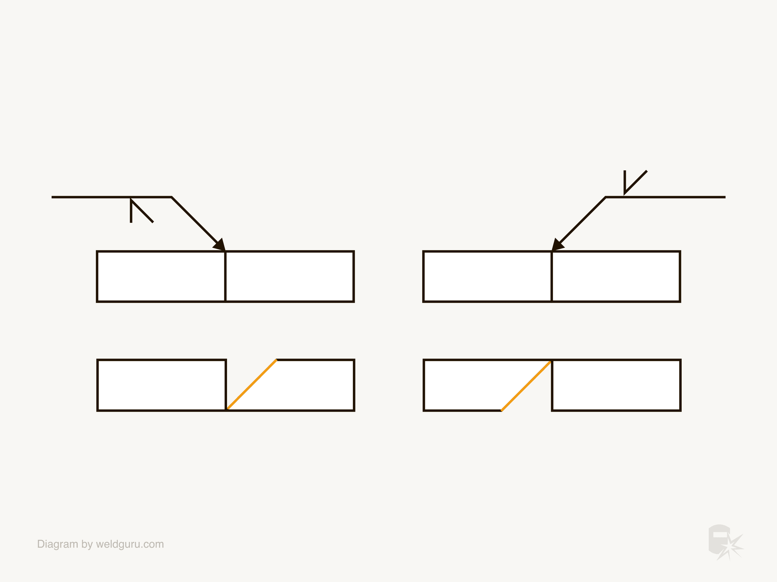
The arrow points to the plate you need to prep. In the examples above:
On the left side: the arrow points to the plate on the right side of the joint, and the weld symbol is on the arrow side of the reference line. In this case, you prep the right side plate from the top side.
On the right side: the arrow points to the left side of the joint, and the symbol is on the other side of the reference line. So, in this case, the bevel is on the left side of the joint and the bottom of the plate.
© weldguru.com – Image usage rights
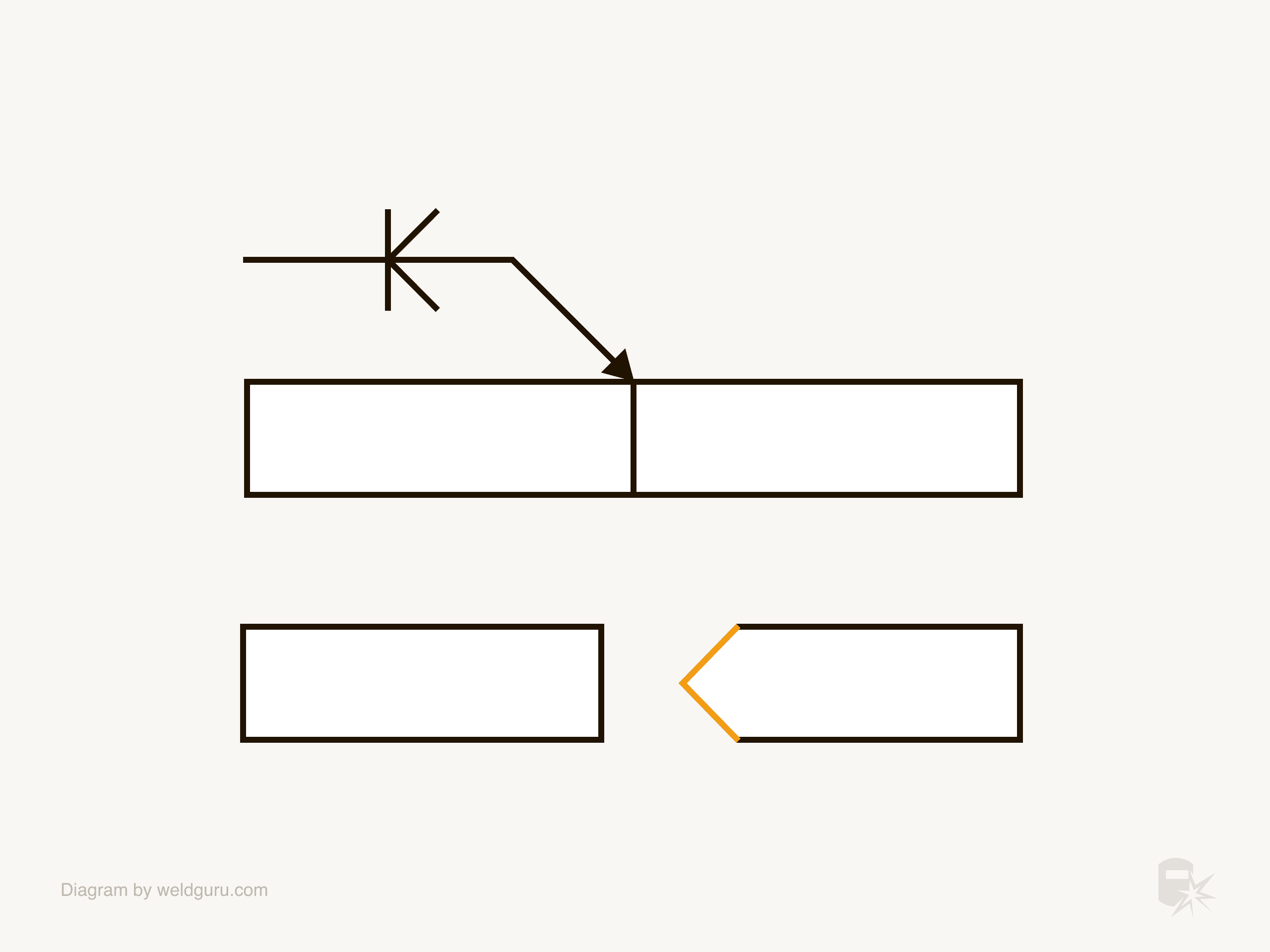
This example shows a single-groove weld symbol on both sides of the reference line. The arrow points to the right side of the weld joint, so you want to bevel both sides of the joint on the right side plate.
This interpretation applies to all single-groove weld symbols; the only thing changing is the weld preparation type.
V Groove Plate Preparation
A V groove weld symbol will have both plates getting a weld prep. This means which plate the arrow points to is unimportant, but you still need to understand which side of the joint gets the weld prep.
This is very important because sometimes, in cases where welding is on both sides, there needs to be less weld prep on one side than the other.
Like with the single groove symbols, you’ll look at which side of the reference line the weld symbol is on.
© weldguru.com – Image usage rights
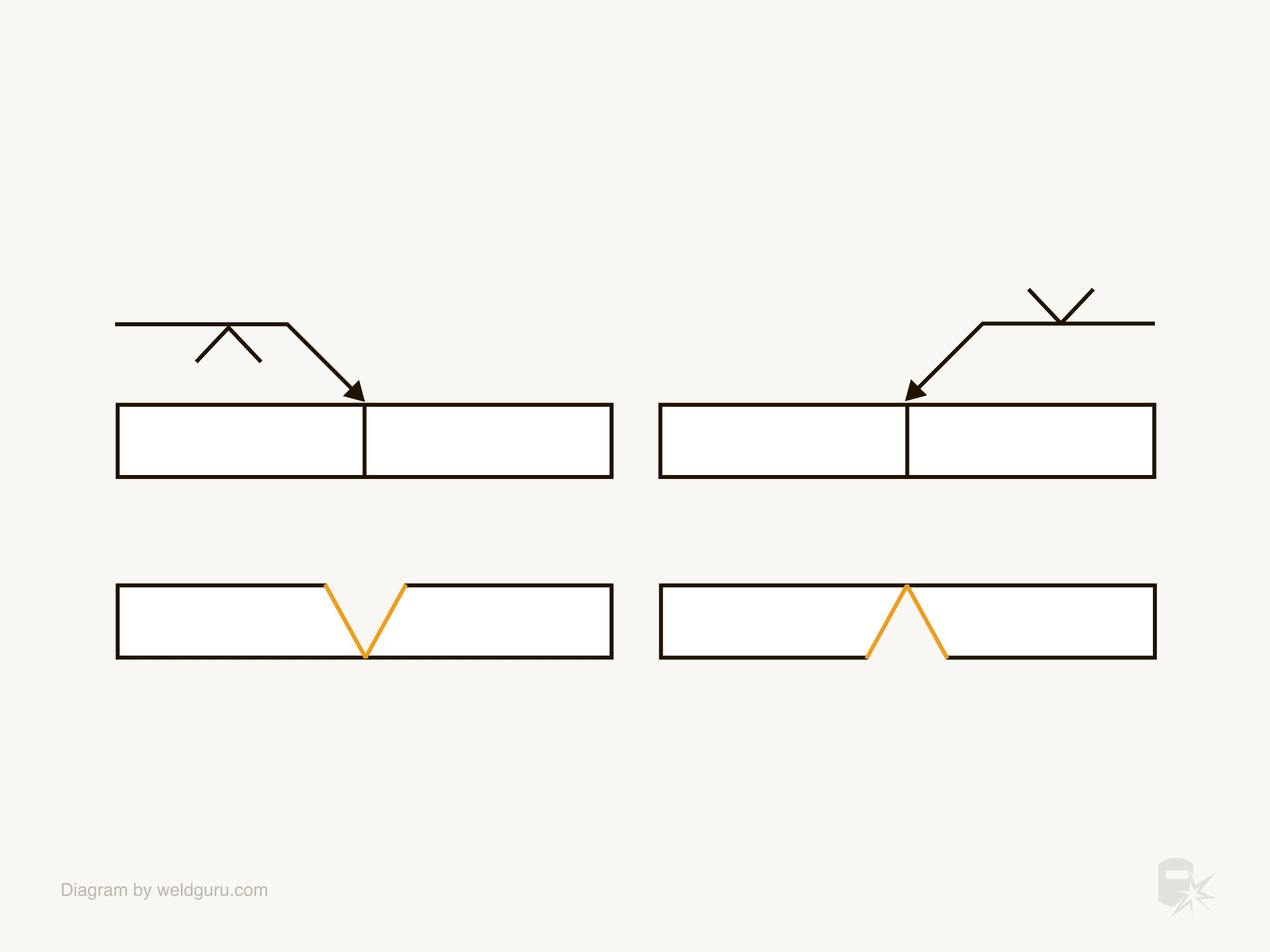
In these examples:
The left side: This has a V groove weld symbol on the arrow side of the joint. In this case, you’ll bevel both sides of the weld joint from the top side of the plate.
The right side: This symbol is on the other side of the reference line, so you’ll bevel the bottom side of the plate and both sides of the joint.
© weldguru.com – Image usage rights
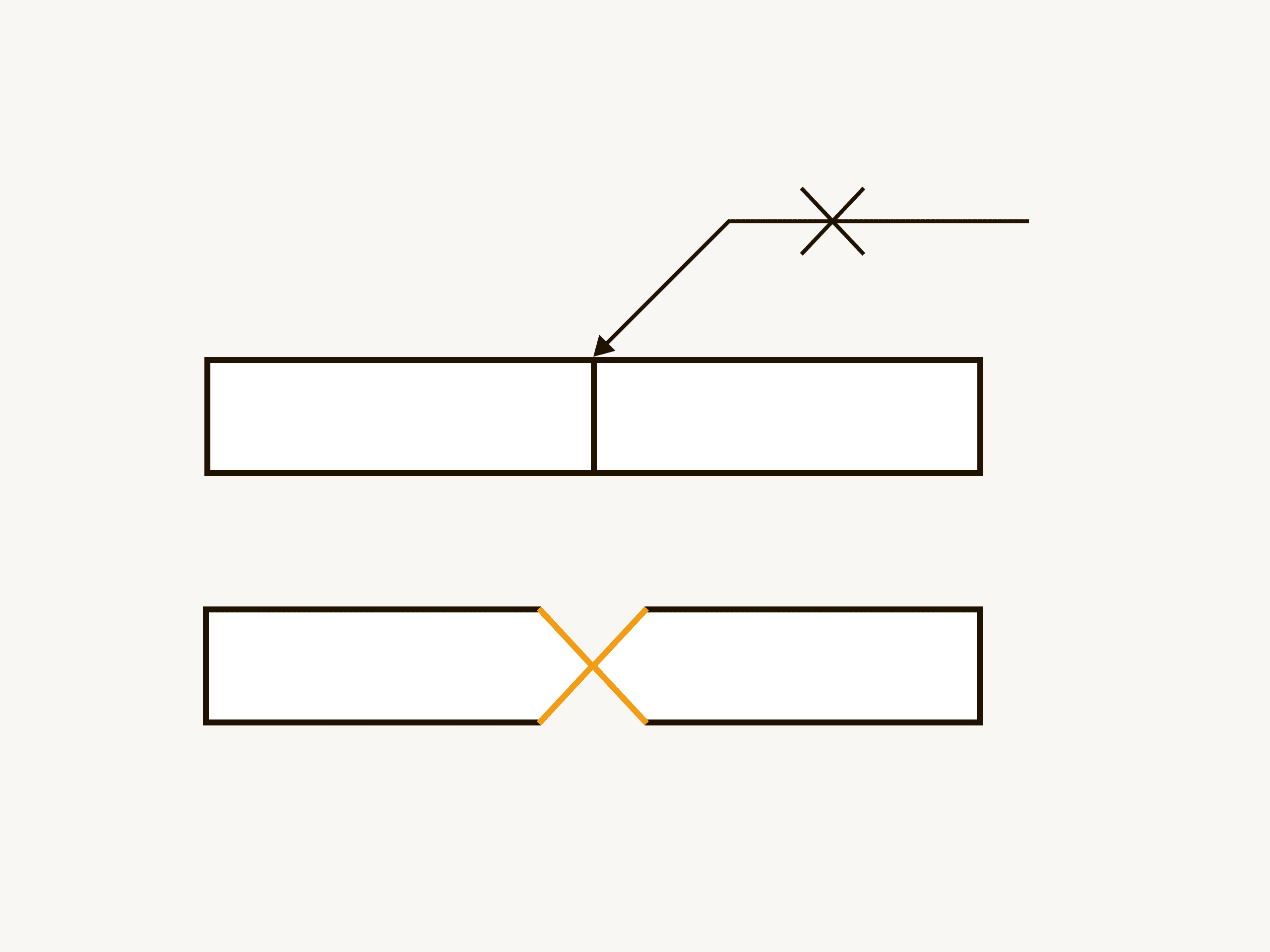
When you see a V groove symbol on both sides of the reference line, you’ll be beveling from either side of the joint. If there are no depths of preparation listed, you’ll bevel the plates to the middle so they meet at a point.
Break In The Arrow
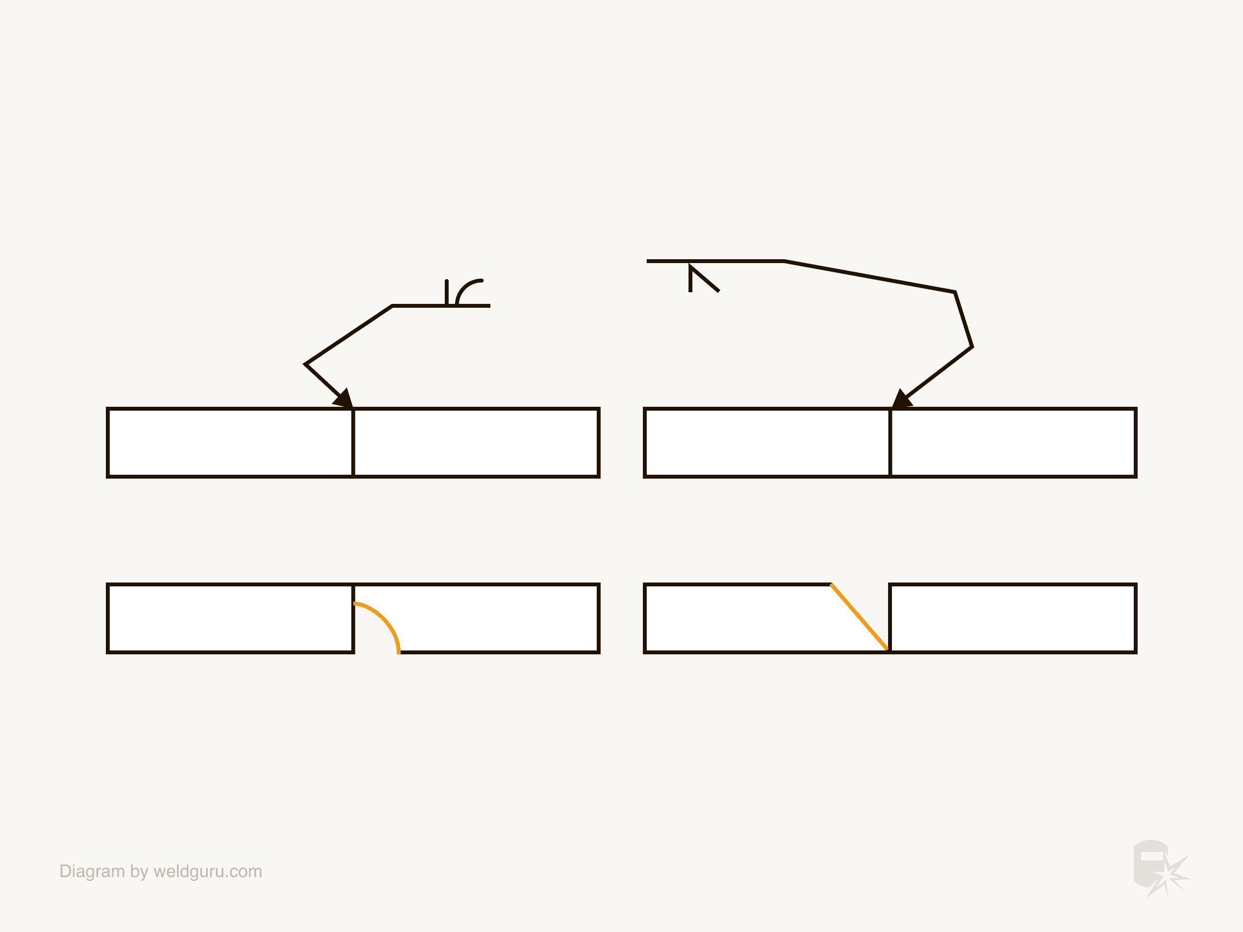
Sometimes, you’ll notice a break in the arrow line, called a break or a jog. You’ll see this when the engineer or draftsperson needs to move the direction in which the arrow points.
© weldguru.com – Image usage rights
For single-groove joints, the arrow must point to the correct side of the joint. You’ll see a jog when the welding symbol is in a position where the arrow wouldn’t naturally point to the proper plate, which needs preparation.
For V groove welds, a jog or break only makes placing the welding symbol on the blueprint easier because both plates get beveled.
Groove Weld Preparation in Other Weld Positions
Groove welds are not exclusive to butt joints. You may see them on joints such as a T-joint.
In this case, you must pay close attention to the weld symbol to prepare the joint appropriately.
© weldguru.com – Image usage rights
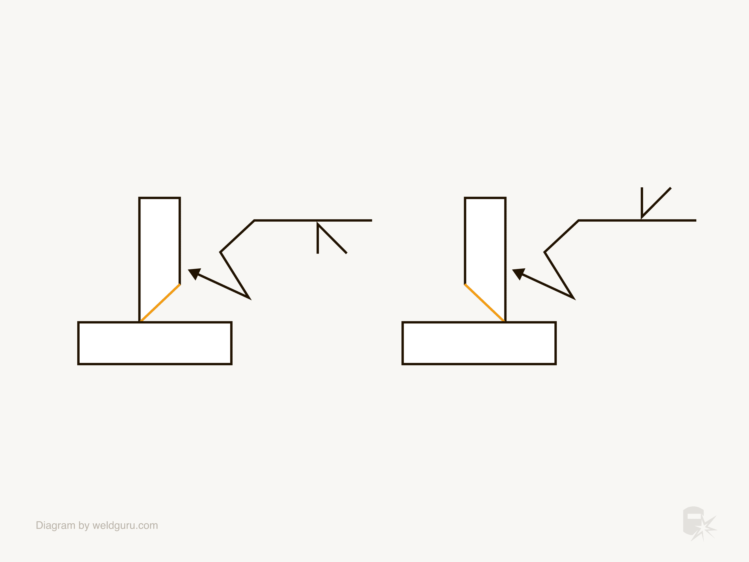
In the example above:
The left side: Shows a weld symbol on the other side of the reference line, so you’ll put the bevel on the opposite side of the plate the arrow is pointing to.
The right side: The weld symbol is on the arrow side of the reference line, so you’ll bevel the plate on the side the arrow is pointing to.
Depth of the Bevel
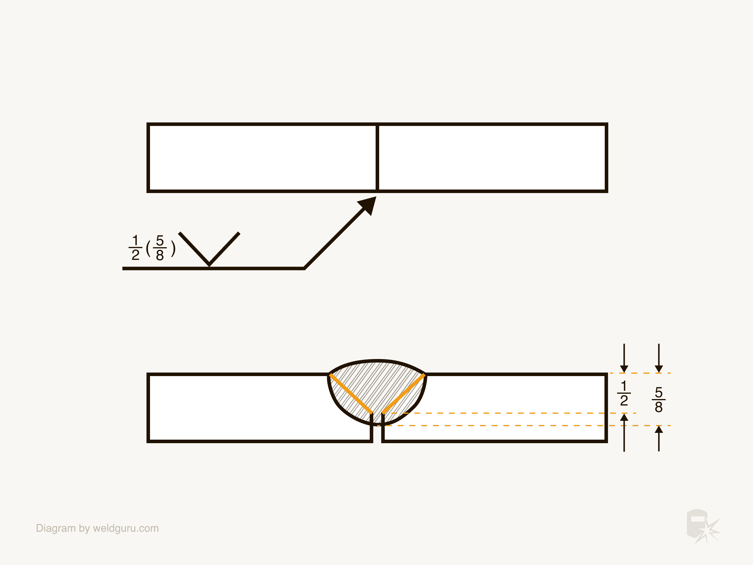
A weld bevel may not extend to the other side of the weld joint. In these cases, you’ll see dimensions to the left of the weld symbol. These numbers are the depth of preparation and depth of penetration.
The depth of preparation is the distance the weld prep extends down into the weld joint. The depth of penetration is how far the weld metal should extend into the weld joint.
The depth of penetration will be in brackets, separating it from the depth of preparation.
© weldguru.com – Image usage rights
In the example image above, we see a V groove weld symbol that indicates that the weld is on the other side of the weld joint and gets a ½” depth of preparation, and the weld needs to penetrate ⅝” into the weld joint.
© weldguru.com – Image usage rights
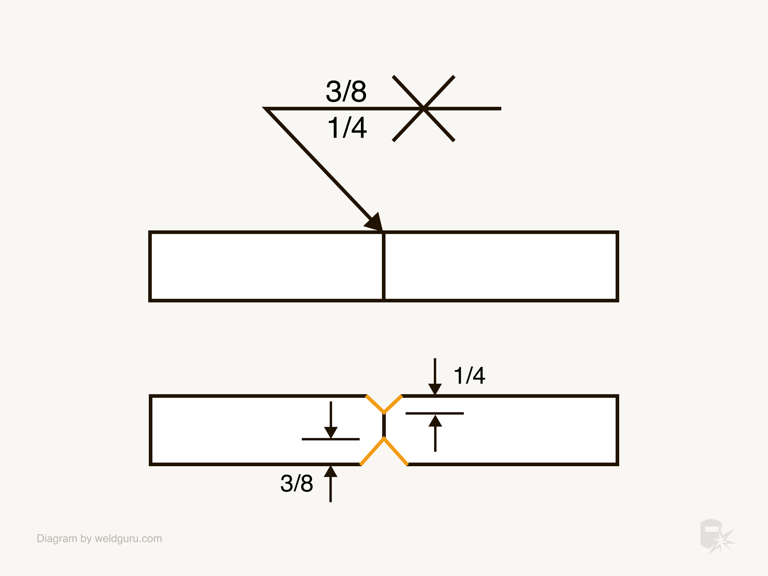
This next example above illustrates how to prep a joint where there are different depths. In this case, the arrow side of the joint has a ¼” depth, while the other side has a ⅜” depth.
If no depth of preparation is listed, you’ll bevel the joint all the way through, or in the case of a symbol on both sides, to the middle to make a point.
Understanding Groove Angles
There are many times when the welding engineer or the weld procedures need a specific bevel angle cut into the plates.
You’ll find this angle inside the weld symbol itself. The angle listed is the included angle, which means it’s the total angle of the joint.
How you prepare the joint differs depending on which type of groove weld, so I’ll break each into its own sections.
Bevel Groove Angles
© weldguru.com – Image usage rights
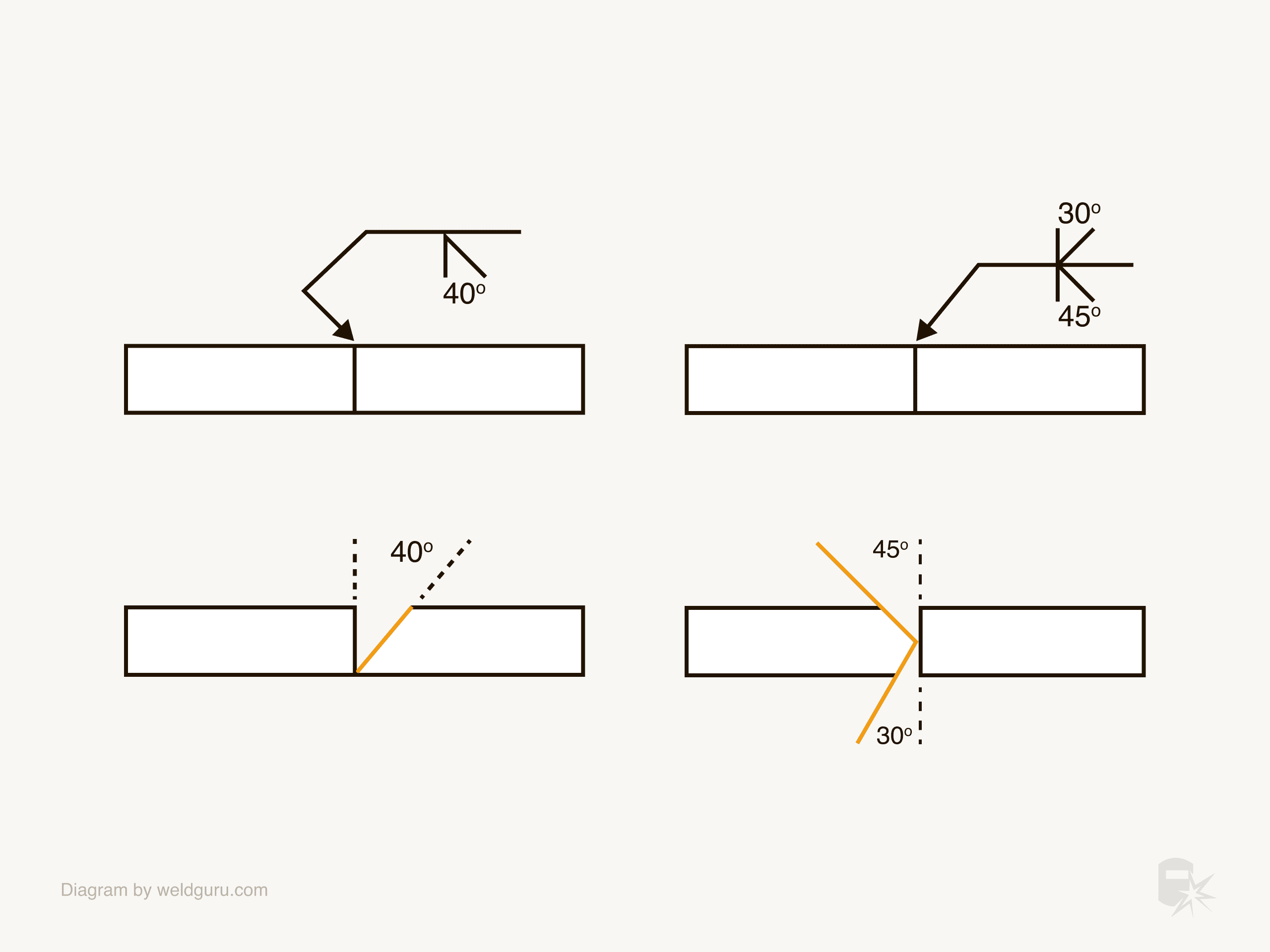
The angle for a bevel groove is the angle at which you’ll cut the bevel on the plate the arrow points to.
In the example above, the angle of the bevel is 40 degrees on the plate the arrow is pointing to.
If you need to use a different angle for each side of the joint, you’ll see a unique angle on each symbol.
V Groove Angles
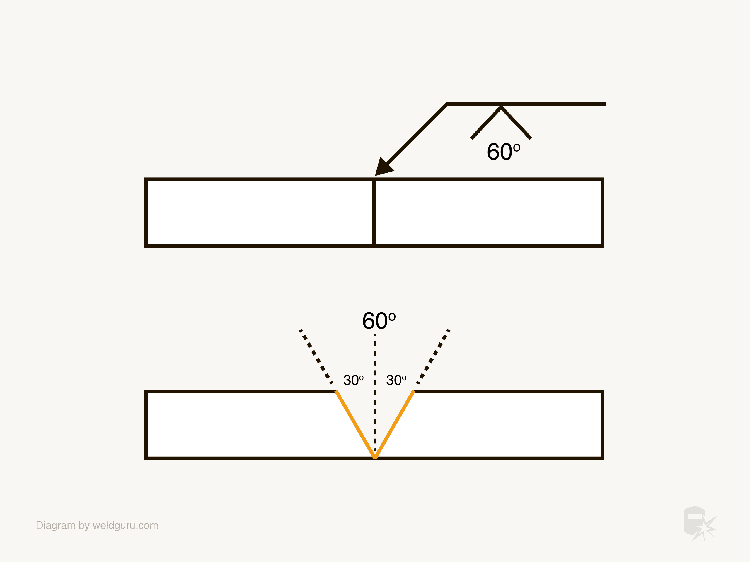
V groove angles are in the same place as they are for the bevel groove, but the angle listed is for the angle of both bevels combined.
© weldguru.com – Image usage rights
The example image above shows a 60-degree included angle; this means you’ll cut a 30-degree bevel into each plate.
© weldguru.com – Image usage rights
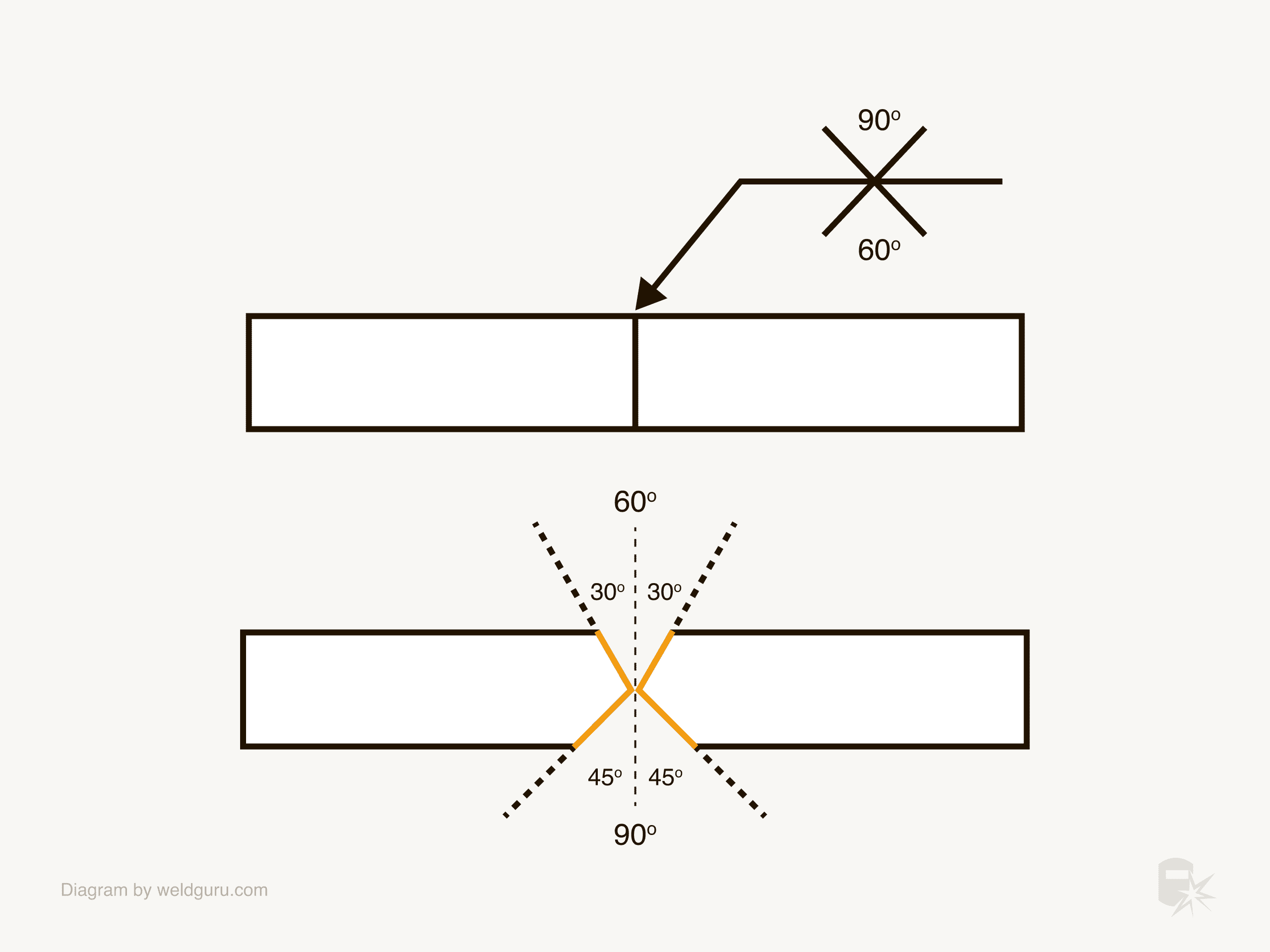
Much like when a bevel groove has a different angle for each side, V groove weld symbols can have a different angle for each symbol.
Remember that this is an included angle, which is the sum of the two bevel angles.
Measuring the Root Opening on Groove Weld Symbols
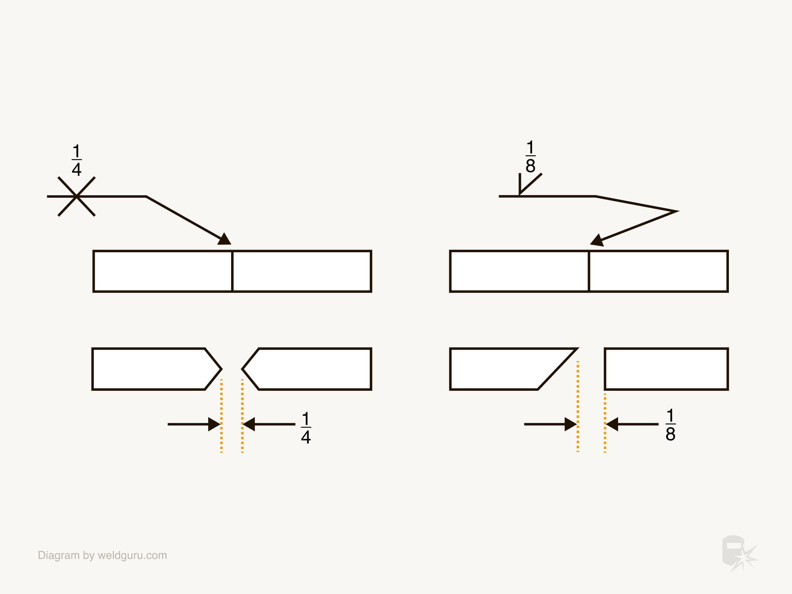
When a groove weld joint needs a gap at the root, the dimension of this gap is inside the weld symbol underneath the included angle.
The root gap is the dimension of the space between the plates at the root of the weld preps. You’ll make this gap during the fit-up process and use the tack welds to keep it at the appropriate dimension.
© weldguru.com – Image usage rights
In the example above:
The left side: The weld calls for a ¼” root gap on a double V groove weld. You’ll measure the gap between the points of the bevels.
The right side: This weld is for a single groove weld with a ⅛” root gap. The gap for this weld measures from the point of the bevel to the flat plate.
© weldguru.com – Image usage rights
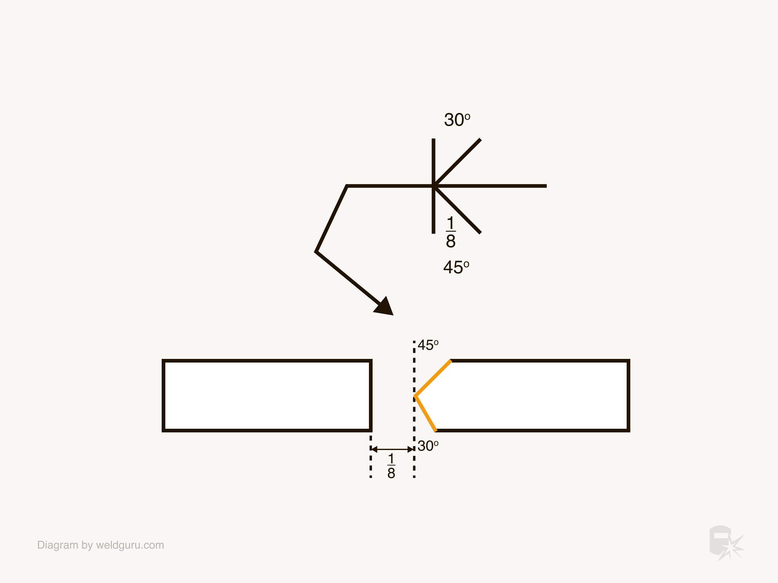
This example shows a ⅛” root opening, but each side of the weld joint has a different angle. In this case, the arrow side is 45 degrees, and the other side is 30 degrees.
While this symbol is more complicated, measuring the root gap is still the same as the other examples.
Wrapping It Up
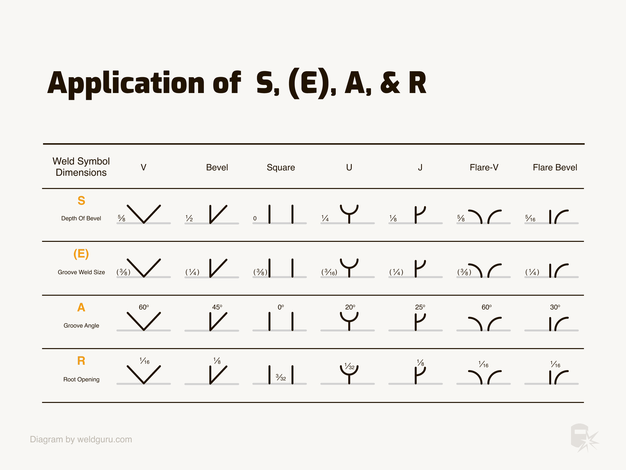
View the full size here
© weldguru.com – Image usage rights
Sometimes, weld symbols look very complicated. However, if you understand their structure, it’s not difficult to break them down and understand what you must do to prepare and weld the joint.
Welding symbols are an essential part of welding. As a welder, you need to develop a robust understanding of them to limit the possibility of making mistakes, as mistakes can be very costly in the welding industry.