Welding symbols guide welders in preparing, welding, and finishing weld joints. All the information you need as a welder is in the welding symbol.
Welding symbols ensure the welder knows what the engineers and designers of the product intended for the welding.
Understanding welding symbols is critical for anyone working in a fabrication shop because it’s the best and most effective way for the engineers to provide the welder with the necessary information to do their job correctly according to welding codes.
The American Welding Society (AWS) publishes and maintains a national standard for welding symbols in the USA to ensure universal standards for welders.
The standard’s official name is “ANSI/AWS A2.4 Standard Symbols for Welding, Brazing, and Nondestructive Examination.”
The International Organization for Standardization (ISO) also maintains an international standard in ISO 2553.
The two standards have subtle differences, but the basic premise is the same.
Understanding Weld Symbols: An Overview
A welding symbol is a picture with multiple parts that contain information to inform the welder about how to proceed.
This section aims to break down the structure of the welding symbol, making it easier to digest and understand.
Basic Structure of a Welding Symbol
© weldguru.com – Image usage rights
It’s important to note that the terms “weld symbol” and “welding symbol” are not interchangeable.
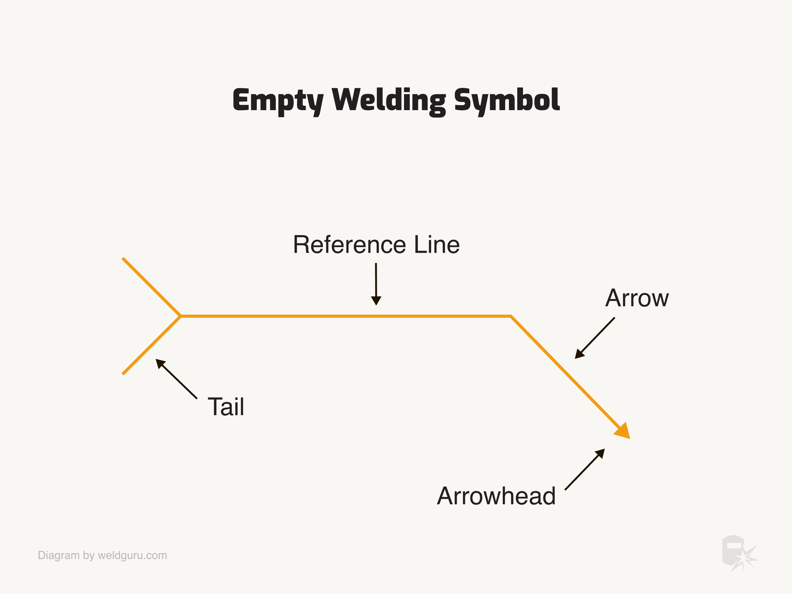
A welding symbol is what you see above and contains the arrow, reference line, and tail. You can remove the tail if there’s no information needed in it.
You place a weld symbol on the reference line of a welding symbol to indicate what type of weld you require.
1. Reference Line
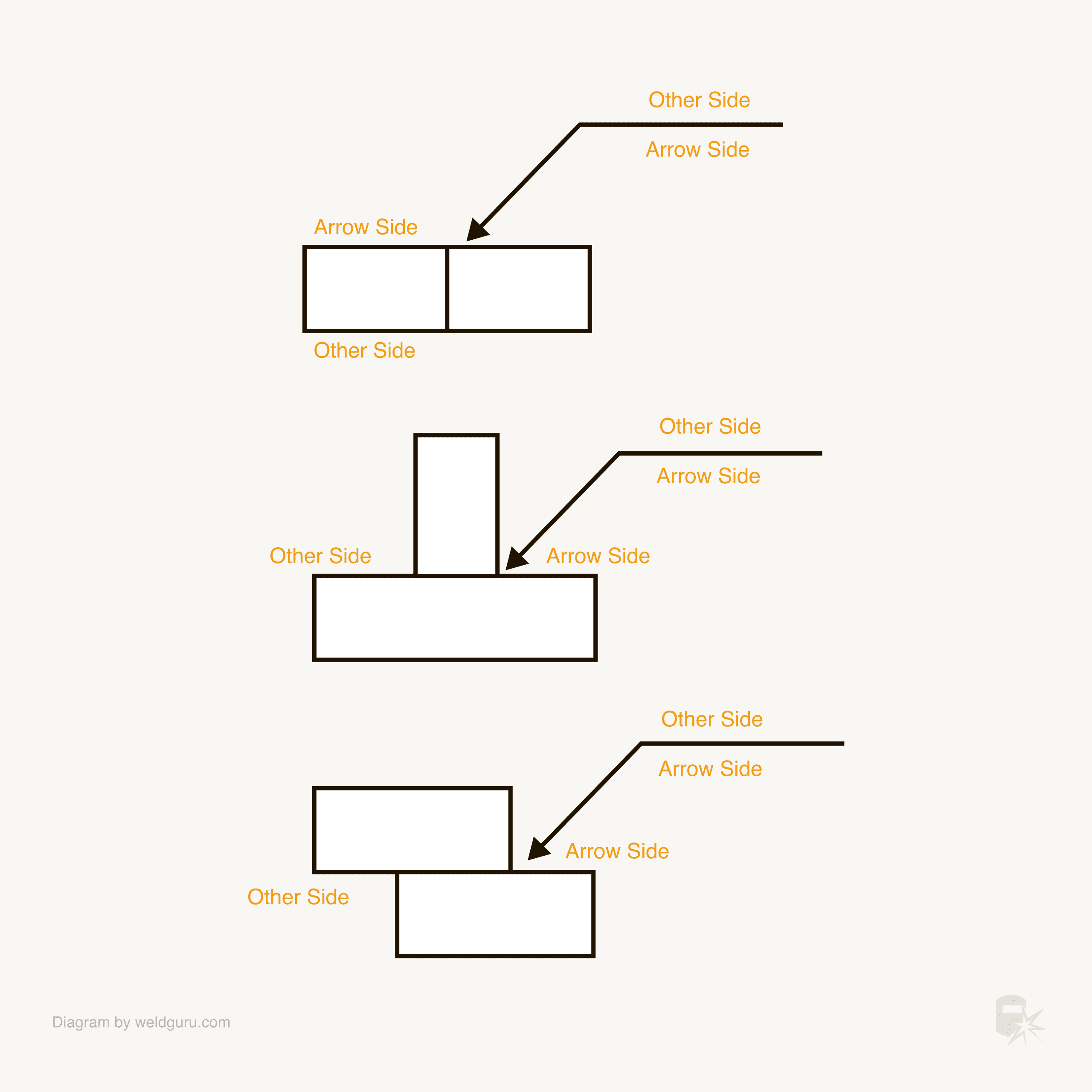
The reference line is the main component of the welding symbol and contains the bulk of the information for the welder. The AWS system separates the reference line into “arrow side” and “other side.”
© weldguru.com – Image usage rights
Regardless of how the arrow points, the top side of the reference line is the “other side,” and the bottom side is the “arrow side.”
The ISO standard uses a dashed line underneath the reference line to hold the information for a weld on the opposite side of the weld joint.
Some examples of the information on the reference line are the type of weld, size, contours, spacing, length, and root opening.
2. Arrow
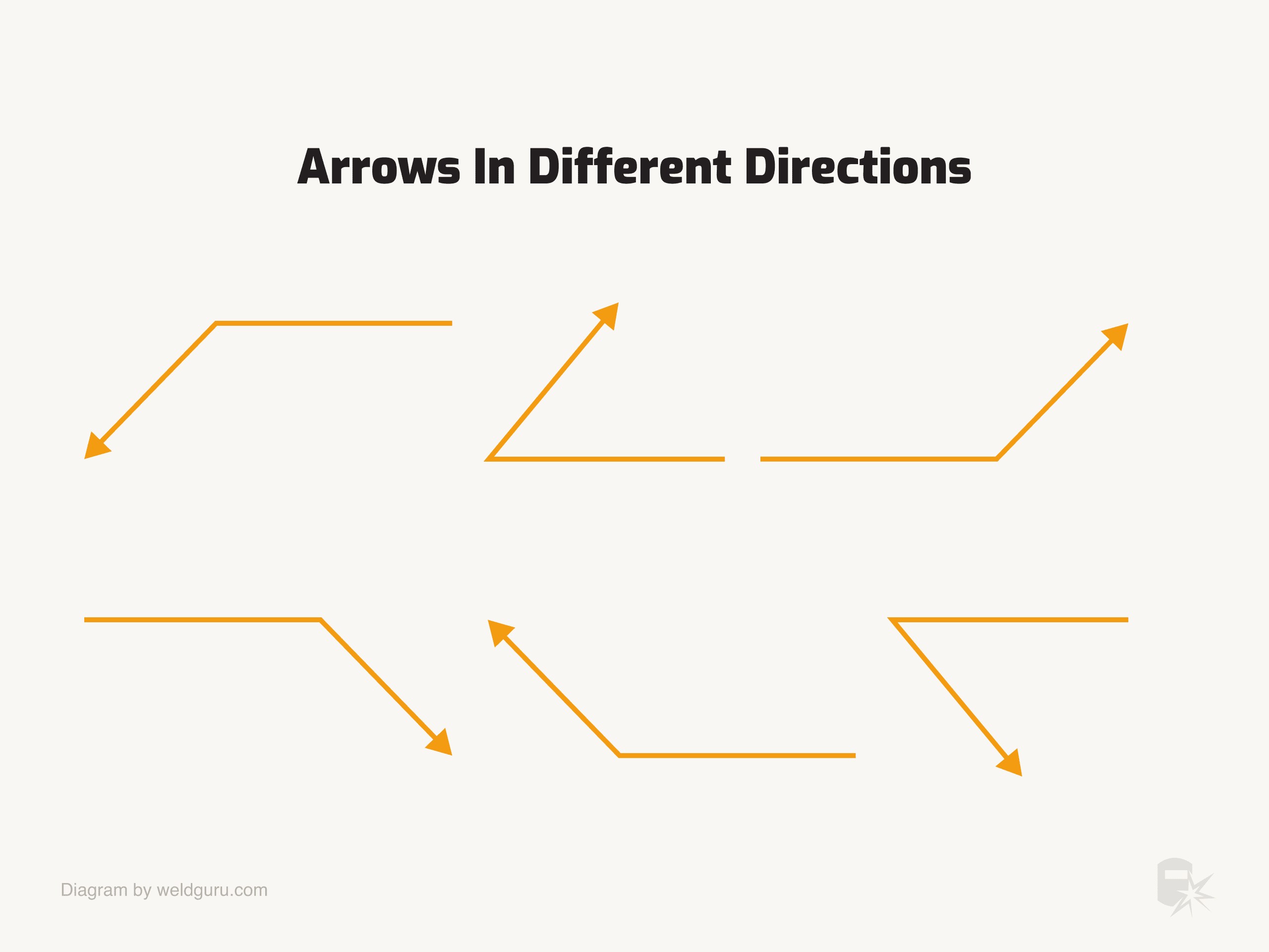
The arrow is a critical component that connects the reference line and points to the location where you’ll apply the weld. The arrow can have many combinations and can point either up or down.
© weldguru.com – Image usage rights
While the arrow’s goal is to show you which joint you’ll weld, it also designates which side is the “arrow side” of the weld joint.
In the case of groove welds, it’ll tell you which side of the joint gets the weld prep.
3. Tail
The tail of the weld symbol is where you would find the specifications for the welding process or information that doesn’t fit in other areas of the weld symbol.
For example, if the engineer wants you to weld the joint with MIG, they’ll put “GMAW” in the tail of the welding symbol.
Basic Elements of a Welding Symbol
© weldguru.com – Image usage rights
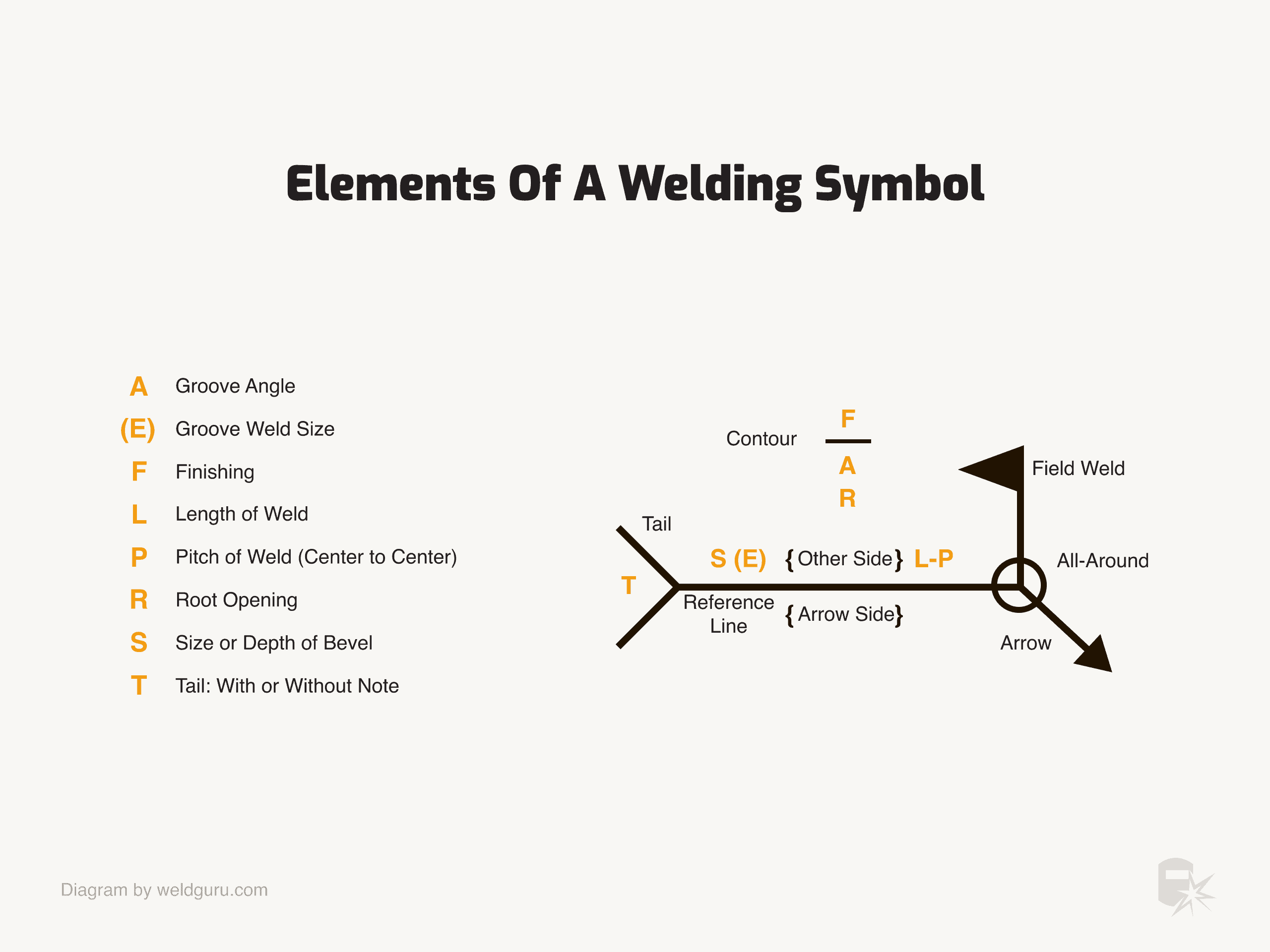
An assembled welding symbol consists of the following seven elements or any of these elements as necessary:
- Reference line: This is where the symbols sit.
- Arrow: Points to the joint or particular side of the joint.
- Basic weld symbols: These sit on the arrow or the other side of the reference line, indicating the type of weld.
- Dimensions & other data: These are placed on either side of the weld symbol or above it, specifying the size, length or pitch of the weld.
- Supplementary symbols: Provide additional information about the weld, such as the need for an all-around weld or a field weld.
- Finish symbols: Indicate the surface finish requirements of the weld, such as grinding or machining.
- Tail: Contains specific instructions, notes, or references for the welding process.
- Specification, process, or other references: These are often included in the tail and specify the welding or cutting process, reference to the welding procedure, and other data not explicitly covered by the basic symbols or dimensions.
The image above shows the information in a typical welding symbol. On the reference line, there will be a weld symbol; above this symbol may be information about the weld finish, contour, groove angle, and root opening.
To the left of the weld symbol is the size of the weld for a fillet weld or the depth of preparation for a groove weld. In the case of a groove weld, there may also be another dimension in brackets: the depth of penetration.
To the right of the weld symbol is the length and pitch of the weld for a staggered weld.
Types of Weld Symbols
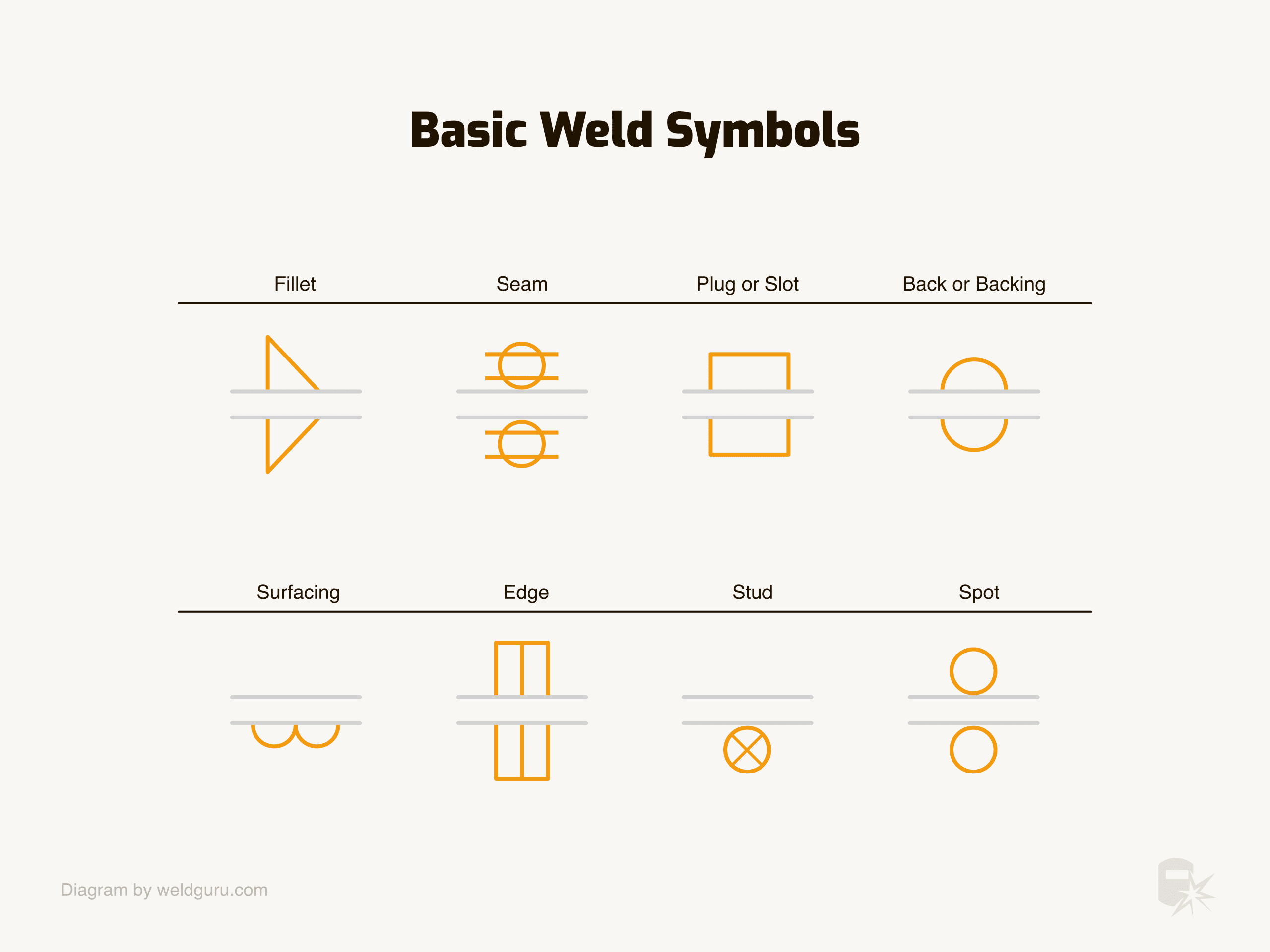
Many types of weld symbols sit on the reference line, and knowing what type of weld each of these symbols asks for is critical.
Basic Weld Symbols
© weldguru.com – Image usage rights
The basic weld symbols are essential to understand so you’ll know what type of weld to do and the required preparation.
Fillet Weld
© weldguru.com – Image usage rights
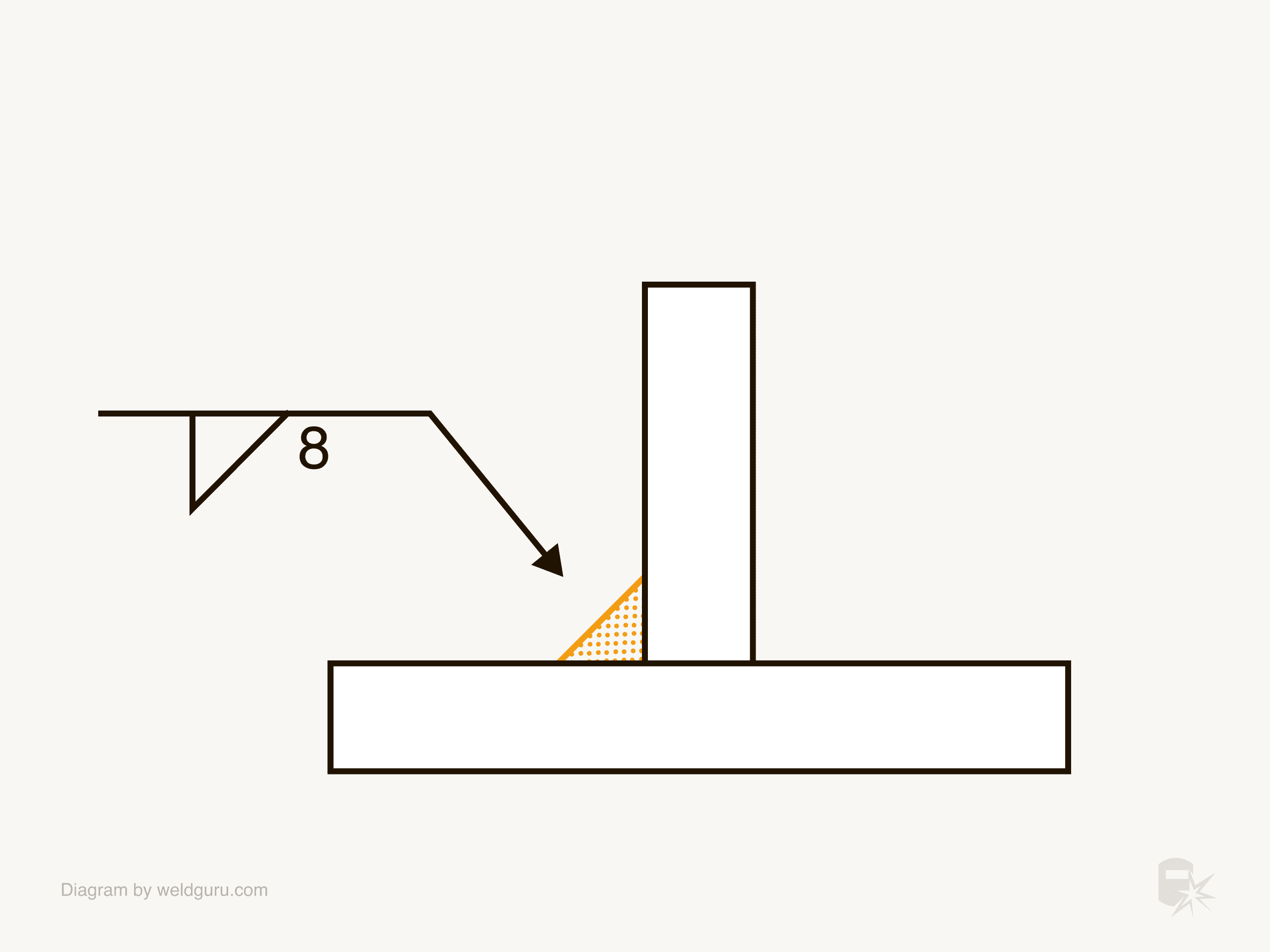
Fillet welds are some of the most common welds you’ll encounter. This symbol can be on either side of the reference line or both sides.
If the symbol is on both sides but offset slightly from each other, the weld is to be a staggered stitch weld.
Learn more about how to read fillet weld symbols in this guide:
Plug or Slot Weld
Plug and slot welds joint overlapping pieces of metal. You can see this symbol on either side of the reference line but not on both sides.
In the case of a plug weld, the symbol will have the diameter of the weld, the number of welds, and center-to-center spacing between the welds.
Slot weld symbols will have the number of slots, the width and length of the slot, and the center-to-center spacing between welds.
Read more about plug & slot welding symbols here
Spot or Projection Weld
A spot weld joins two overlapping pieces of metal but doesn’t have the preparation of a plug or slot weld. You usually use them on sheet metal with a spot welding machine or a TIG welder.
Like plug or spot welds, you won’t find this symbol on both sides of the reference line. Yet, they can be in the middle of the reference line, indicating no arrow side or other side significance.
Stud
Stud welding uses a special welding gun, which fuses a stud to the surface of a metal plate. You’ll see the size of the stud, the number of studs, and the spacing between them, along with the stud weld symbol.
You only find stud welding symbols on the arrow side of the reference line.
Seam
Seam welding is a form of resistance welding that requires specialized equipment. You can use it to join metal sheets in a continuous weld.
You can’t find seam weld symbols on both sides of the reference line. They can be in the middle of the reference line, indicating no arrow side or other side significance.
Back or Backing
While the symbol for a back weld and a backing weld are the same, there’s an important difference between the two. You do a back weld after the main weld and a backing weld before the main weld.
The tail of the welding symbol will detail which type of weld you need to use. The back or backing weld symbol will only be on the opposite side of the reference line from the main weld symbol.
Surfacing Welds
You’ll see surfacing welds where a surface needs layers of metal added for added wear resistance. When there’s a dimension listed, it will refer to the minimum height of the weld bead. You only find these weld symbols on the arrow side.
Edge
An edge weld is normally only found on sheet metal. You may see a weld size, which will refer to the depth of penetration, not the size of the weld bead.
Edge weld symbols can be on either side of the reference line or both sides.
Groove Weld Symbols
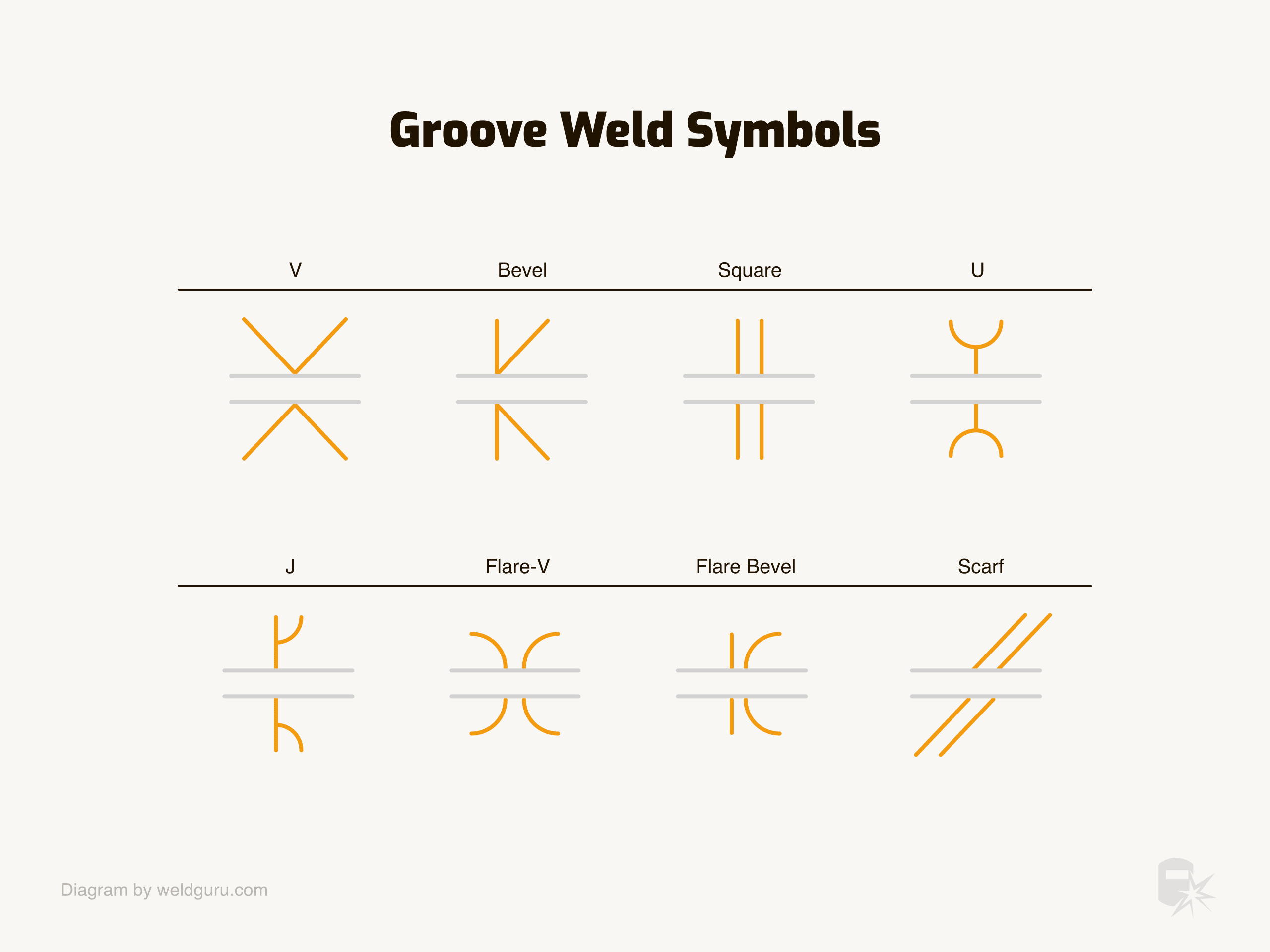
Groove welds are also very common in the welding industry, and you’ll find them anywhere two pieces of steel butt together.
© weldguru.com – Image usage rights
You can find groove weld symbols on either side or side of the reference line.
The type of weld symbol determines the type of joint preparation you’ll be using.
It’s important to understand the structure of the symbol so you’ll know the exact parameters of the joint preparation.
© weldguru.com – Image usage rights
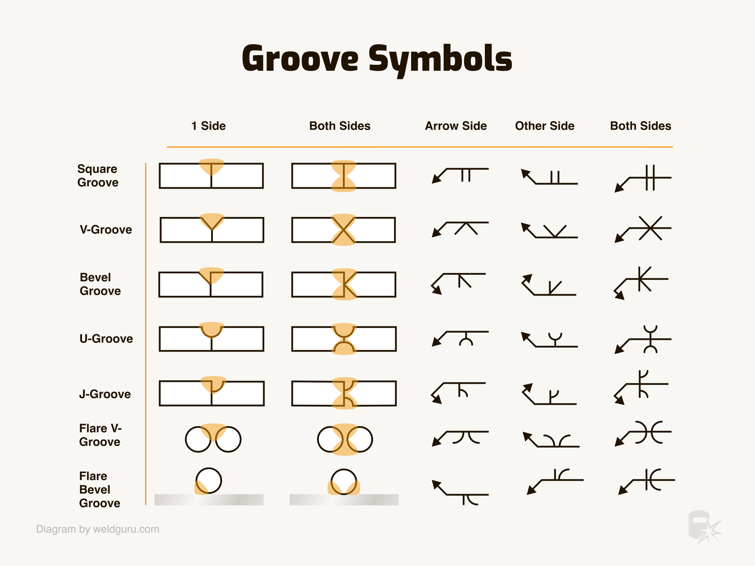
V-Groove Welds – A V-groove weld has bevels cut on both sides of the weld joint. Like a bevel weld, the plate edges get cut at an angle. There may be an angle above the V groove weld symbol, which is the included angle of the bevels.
Bevel Groove Welds – A bevel groove weld has a bevel cut into only one side of the joint. The arrow of the welding symbol will point to the side of the joint that needs the bevel. There will often be an angle above the weld symbol telling you the angle at which to cut the bevel.
U-Groove Welds – U-groove welds aren’t as common as bevel or V-groove welds but are still important to understand. Instead of a flat bevel, a U groove has a rounded and concave preparation. This shape gives more space for the weld to wash into the joint. These are not common and are more expensive to prep, as you must machine them.
J Groove Welds – J groove welds are the same as the bevel weld except for the preparation. The weld prep has a concave profile resembling a J in shape. These are not common and are more expensive to prep, as you must machine them too.
Flare V Groove Welds – You often see flare V groove symbols when you weld two pieces of HSS together, and the radiused corners of the tube make up the weld joint. Like the flare bevel joint, a depth of penetration might have an indication.
Flare Bevel Groove Welds – You’ll often see this weld symbol when you weld something round, like a round bar, to a flat plate. The weld requires no preparation, but the symbol may indicate the required depth of penetration.
Learn more about how to read groove weld symbols in this guide.
How To Read Fillet Weld Symbols
© weldguru.com – Image usage rights
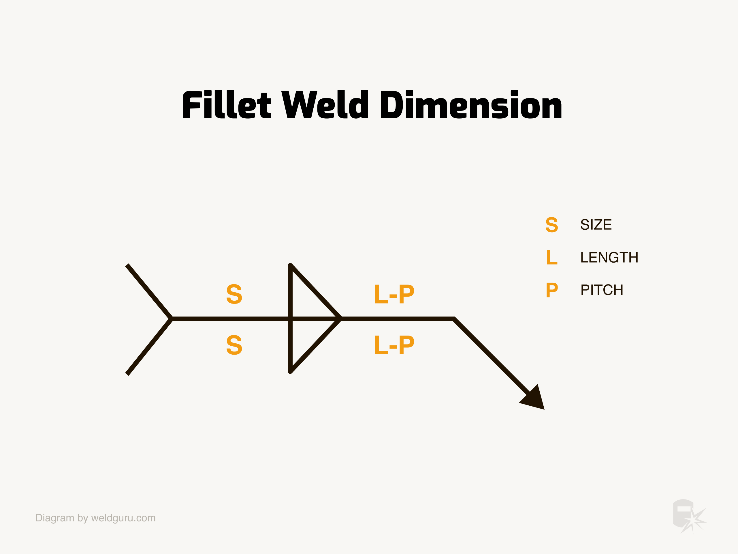
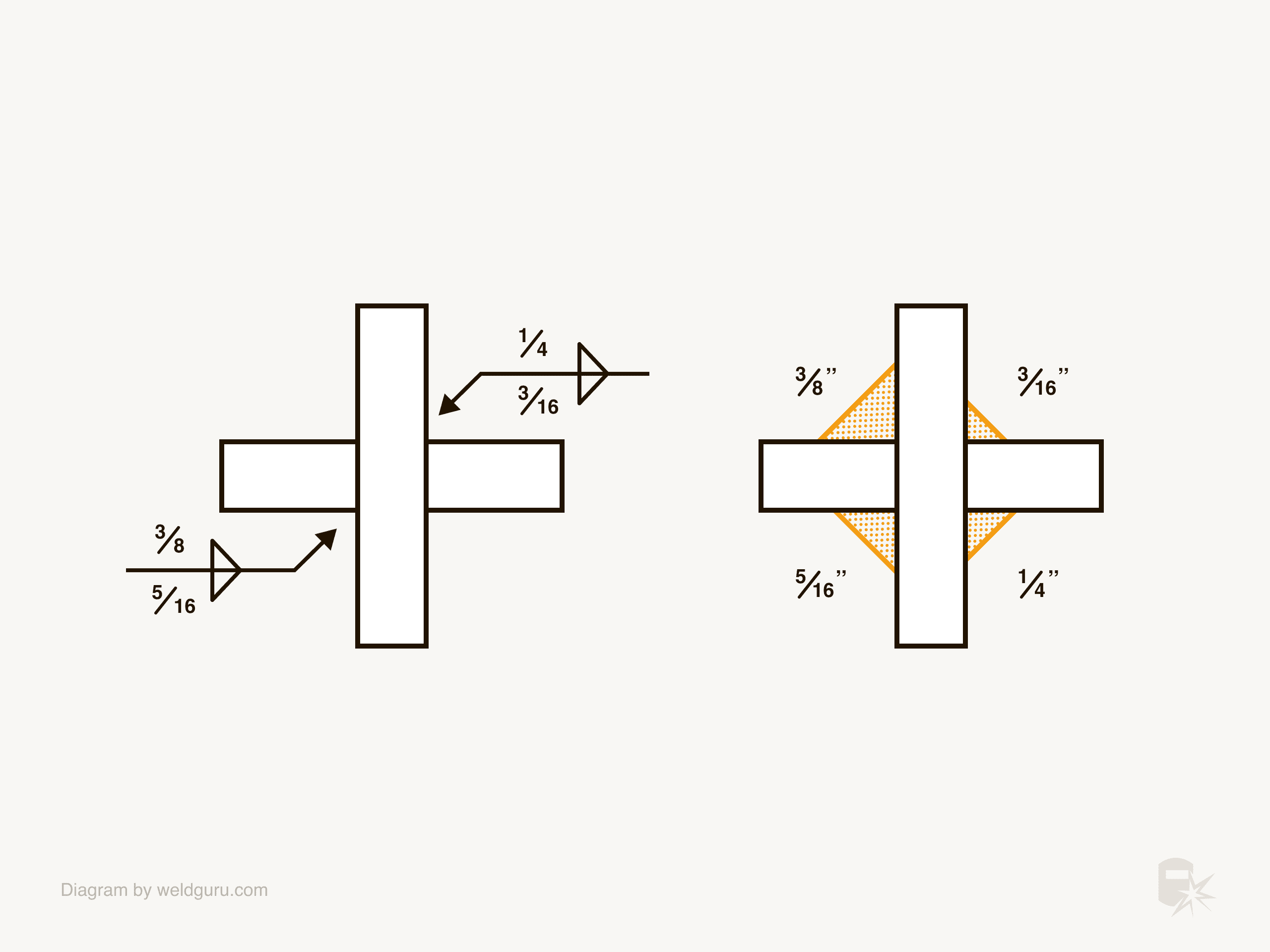
To the left of a fillet weld symbol is the size of the weld, which is the letter “S” in the above diagram. The weld size refers to the leg length of a fillet weld.
For example, a ⅜” fillet weld will have both legs of the weld measuring ⅜” from the plate to the toe of the weld.
© weldguru.com – Image usage rights
If the welding symbol has no size listed, then the weld size equals the thickness of the thinnest of the plates that you’re welding together.
You’ll use a fillet gauge to confirm that a fillet weld is the correct size.
© weldguru.com – Image usage rights
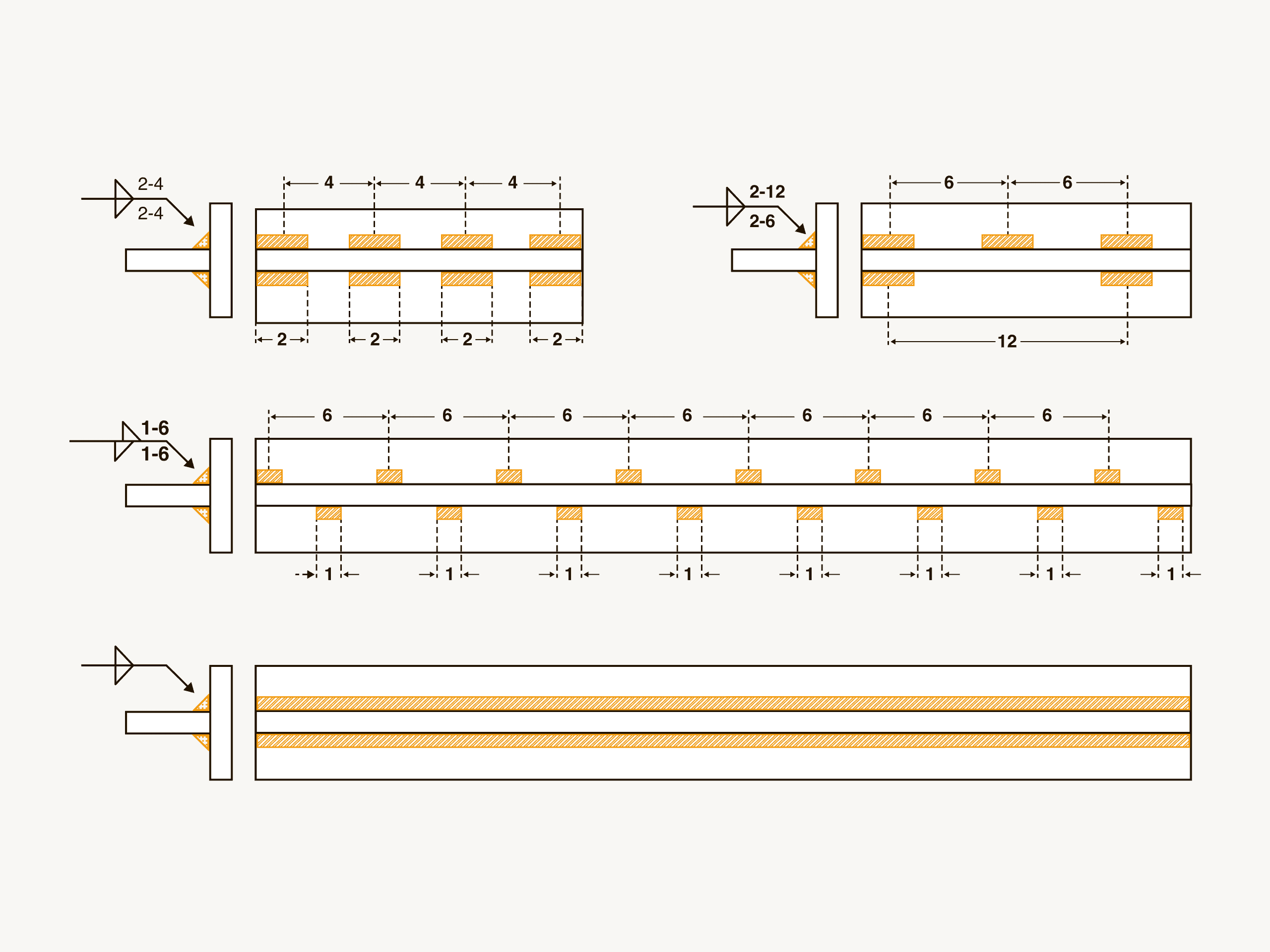
To the right of the weld symbol is the length and pitch of stitch welds (L and P). Length refers to the length of each stitch weld, and the pitch is the center-to-center spacing between stitch welds.
When the filet weld symbols look slightly offset, the weld is a staggered stitch weld. If there is nothing listed, the weld is continuous.
Learn more about how to read fillet weld symbols in this guide.
How To Read Groove Weld Symbols
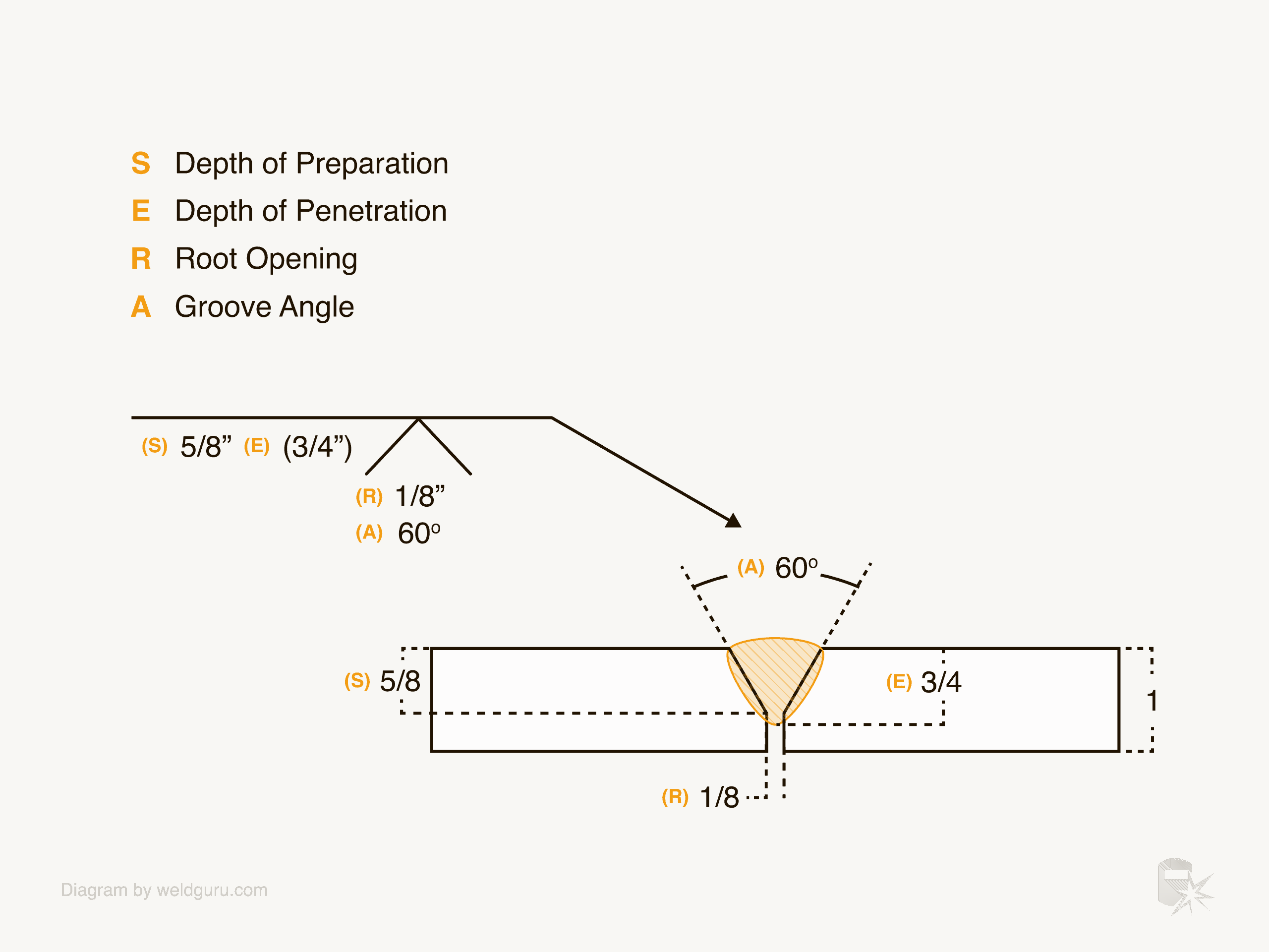
The groove weld symbols tell you what type of joint preparation you’ll need. They also tell you the angle of the joint preparation, depth of the preparation, depth of penetration, and the root opening, if required.
© weldguru.com – Image usage rights
Above is an example of the structure of a groove weld. Inside the weld symbol is the dimension for the root opening (R), and below that is the groove angle (A).
The groove angle is the included angle of the joint, not the angle you cut the bevel. For example, a 60-degree included angle is two 30-degree bevels.
To the left of the symbol is the depth of preparation (S) and the depth of penetration (E). The depth of preparation is the dimension from the top of the plate to the point where the weld prep ends.
The penetration depth is the distance from the top of the plate to the root of the weld. The depth of penetration will be in brackets.
Learn more about how to read groove weld symbols in this guide:
CJP & PJP
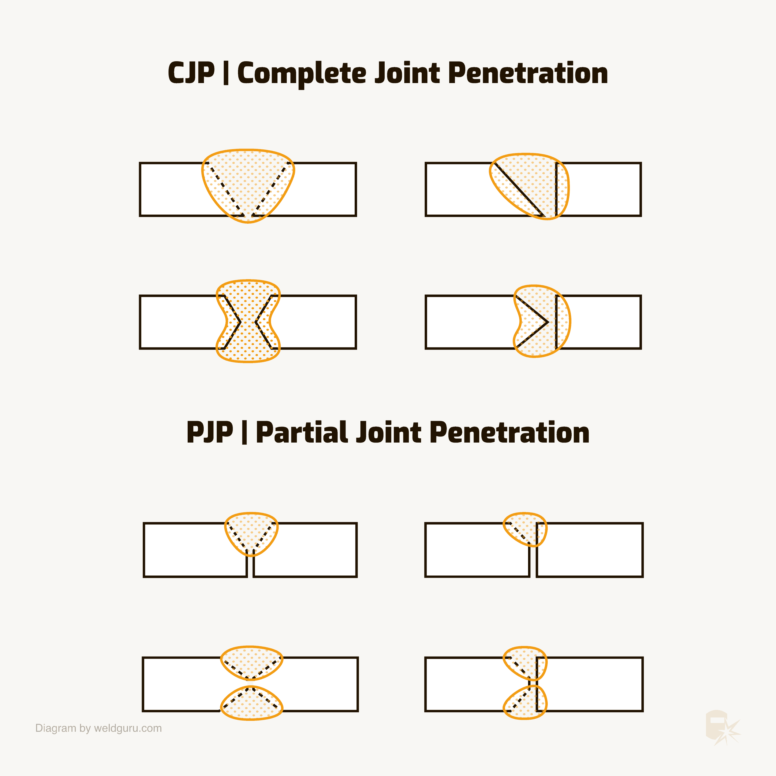
When you’re welding any weld joint, it can be either a complete joint penetration (CJP) or partial joint penetration (PJP).
© weldguru.com – Image usage rights
A CJP weld is also a 100% weld and requires clean, effective weld metal to penetrate the entire weld joint, leaving no seam or gap between the plates.
To indicate a CJP weld, the engineer will put “CJP” in the tail of the welding symbol.
A PJP weld does not require the weld metal to penetrate the root of the joint. A PJP weld isn’t very common.
Supplementary Symbols
© weldguru.com – Image usage rights
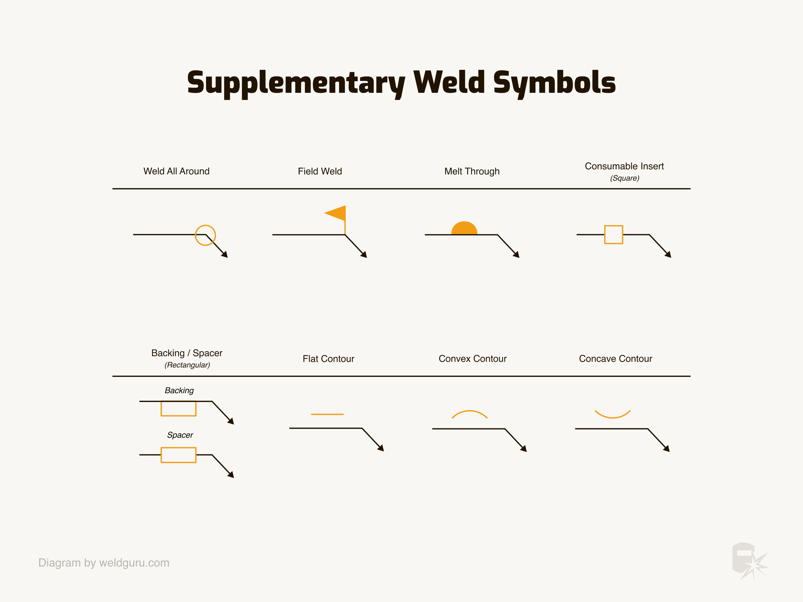
Several supplementary weld symbols are important to understand.
These symbols give you added information about the weld you need to know and understand before fabrication.
All Around – The all-around symbol is a circle where the reference line bends to form the arrow. This symbol means that the weld will be all around the weld joint.
Field Weld – The field weld symbol resembles a flag pole sticking up from where the reference line meets the arrow. You’ll see this symbol on welds done on-site. If there is no field symbol, you should perform the weld in a shop.
Melt-Through – In some groove welds, the weld must penetrate to the other side of the joint. This causes a weld to melt through to the backside of the groove weld. If you need to have melt-through in a weld, you’ll see it as a melt-through symbol. This symbol is a black half circle and opposite to the weld symbol.
Consumable Insert – Some groove welds will have an insert that gets consumed by the weld. The symbol for these inserts is a square on the opposite side of the weld symbol.
Backing – There are cases where a groove weld needs a backing bar to achieve 100% penetration. In these cases, you’ll see a backing bar symbol. Backing bars removed after the welding have the letter “R” in the symbol.
Spacer – If the weld needs a spacer in the weld joint, you’ll see a symbol that’s the same as the backing bar symbol but sits in the middle of the reference line.
Flat/Convex/Concave Contour – These symbols tell you what the finished profile of the weld should be. Along with the contour, you may see a letter telling you how to get the profile.
Some examples of these finishing letters are:
- C – Chipping
- M – Machining
- G – Grinding
- H – Hammering
- P – Planishing
- R – Rolling
- U – Unspecified
Knowing what kind of finish the weld needs is important because sometimes, you’ll have to size the weld based on the finishing procedure.
For example, you might need a larger weld to get the appropriate size and finish when using grinding or machining as a finishing process.
Wrapping It Up
Understanding welding symbols is difficult, especially if you don’t see them regularly. I often have to refer to my notes and quick reference cards when I see a symbol I’ve either not encountered or seen in a long time.
I created a downloadable PDF on welding symbols, which you can print and use as a quick reference.
You should also pick up a copy of the AWS handbook, which has a lot of great information on welding symbols.
In my toolbox, I have an entire drawer devoted to handbooks, manuals, notes, and reference cards, some of which are about welding symbols.
