Overview

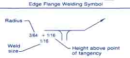
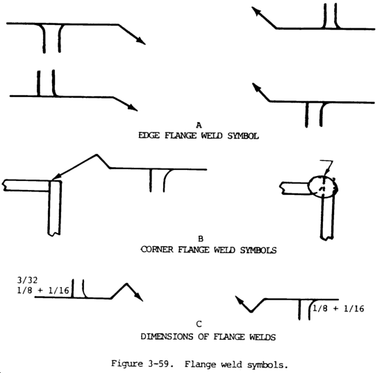
The following flange weld symbols are used for light gauge metal joints involving the flaring or flanging of the edges to be joined (fig. 3-59). These symbols have no arrow or other side significance.
Edge flange welds shall be shown by the edge flange weld symbol (A, fig. 3-59).
Corner flange welds shall be shown by the corner flange weld symbol (B, fig. 3-59). In cases where the corner flange joint is not detailed, a break in the arrow is required to show which member is flanged (fig. 3-59).

Dimensions of Flange Welds
Dimensions of these welds are shown on the same side of the reference line as the weld symbol.
The radius and the height above the point of tangency must be indicated by showing the radius and height, separated by a plus mark, and placed to the left of the weld symbol. The radius and height must read in that order from left to right along the reference line (C, fig. 3-59).
The size (thickness) of the welds must be shown by a dimension placed outward of the flange dimensions (C, fig. 3-59).
The root opening of the welds is not shown on the welding symbol. If the specification of this dimension is desired, it must be shown on the drawing.
Multiple-Joint Flange Welds. For flange welds in which one or more pieces are inserted between the two outer pieces, the same symbol shall be used as for the two outer pieces, regardless of the number of pieces inserted.
Flash or Upset Weld Symbols

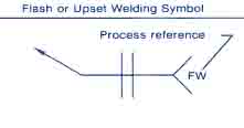
Flash or upset weld symbols have no arrow side or other side significance in themselves, although supplementary symbols used in conjunction with then may have such significance. The weld symbols for flash or upset welding must be centered on the reference line. Dimensions need not be shown on the welding symbol.
Surface Contour
The contour symbols for flash or upset welds (fig. 3-80) are indicated in the same manner as that for fillet welds (see this page for more).
