To ensure the satisfactory performance of a welded structure, the quality of the welds must be determined by adequate testing procedures. Therefore, they are proof tested under conditions that are the same or more severe than those encountered by the welded structures in the field.
This page contains visual inspection tips. The following pages contain inspection methods for GMAW and physical weld testing.
These tests reveal weak or defective sections that can be corrected before the material is released for use in the field. The tests also determine the proper welding design for ordnance equipment and forestall injury and inconvenience to personnel.
NDT refers to nondestructive testing. It is an approach to testing that involves evaluating the weld without causing damage. It saves time and money including the use of remote visual inspection (RVI), x-rays, ultrasonic testing and liquid penetration testing.
In most welds, quality is tested based on the function for which it is intended. If you are fixing a part on a machine, if the machine functions properly, then the weld is often considered correct. There are a few ways to tell if a weld is correct :
- Distribution: Weld material is distributed equally between the two materials that were joined.
- Waste: The weld is free of waste materials such as slag. The slag after cooling should peel away from the project. It should be removed easily. In Mig welding, any residue from the shielding gas should also be removed with little problem. TIG, being the cleanest process, should also be waste-free. In Tig, if you see waste, it usually means that the material being welded was not cleaned thoroughly.
- Porosity: The weld surface should not have any irregularities or any porous holes (called porosity). Holes contribute to weakness. If you see holes it usually indicates that the base metal was dirty or had an oxide coating. If you are using Mig or Tig, porosity indicates that more shielding gas is needed when welding. Porosity in aluminum welds is a key indicator of not using enough gas.
- Tightness: If the joint is not tight, this indicates a weld problem. In oxyacetylene welding, if using autogenous welding, where there is no filler material, the weld must be tight. Same for Tig autogenous welding. The gap is not as critical in other types of welds since any gap is filled in by the filler material. That said, gaps, in general, indicate a potential quality problem.
- Leak-Proof: If you are repairing an item that contains liquid, a leak is a sure-fire way (and obvious way) to see that there is a problem. Same for something that will contain a gas. One testing method is to use soap bubbles to check for problems (can be easily applied with a squirt bottle.
- Strength: Most welds need to demonstrate the required strength. One way to ensure proper strength is to start with a filler metal and electrode rating that is higher than your strength requirement.
Other checks using visual methods include checks before (root face, gap, bevel angle, joint fit), during (electrode consumption rate, metal flow, arc sound and light), and after welding (undercut, root fusion issue, pinholes, excessive spatter, weld dimensions) as described below.
Common Weld Faults
Incomplete Penetration
This term is used to describe the failure of the filler and base metal to fuse together at the root of the joint. Bridging occurs in groove welds when the deposited metal and base metal are not fused at the root of the joint. The frequent cause of incomplete penetration is a joint design which is not suitable for the welding process or the conditions of construction. When the groove is welded from one side only, incomplete penetration is likely to result under the following conditions.
- The root face dimension is too big even though the root opening is adequate.
- The root opening is too small.
- The included angle of a V-groove is too small.
- The electrode is too large.
- The rate of travel is too high.
- The welding current is too low.
Related read: Parts of a Weld – Understanding Weld Nomenclature
Lack of Fusion
Lack of fusion is the failure of a welding process to fuse together layers of weld metal or weld metal and base metal. The weld metal just rolls over the plate surfaces. This is generally referred to as overlap. Lack of fusion is caused by the following conditions:
- Failure to raise to the melting point the temperature of the base metal or the previously deposited weld metal.
- Improper fluxing, which fails to dissolve the oxide and other foreign material from the surfaces to which the deposited metal must fuse.
- Dirty plate surfaces.
- Improper electrode size or type.
- Wrong current adjustment.
Undercutting

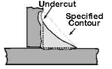
Undercutting is the burning away of the base metal at the toe of the weld. Undercutting may be caused by the following conditions:
- Current adjustment that is too high.
- Arc gap that is too long.
- Failure to fill up the crater completely with weld metal.
Slag Inclusions
Slag inclusions are elongated or globular pockets of metallic oxides and other solids compounds. They produce porosity in the weld metal. In arc welding, slag inclusions are generally made up of electrode coating materials or fluxes. In multilayer welding operations, failure to remove the slag between the layers causes slag inclusions. Most slag inclusion can be prevented by:
- Preparing the groove and weld properly before each bead is deposited.
- Removing all slag.
- Making sure that the slag rises to the surface of the weld pool.
- Taking care to avoid leaving any contours which will be difficult to penetrate fully with the arc.
Read more about the causes and how to prevent slag inclusions here.
Porosity
Porosity is the presence of pockets that do not contain any solid material. They differ from slag inclusions in that the pockets contain gas rather than a solid.
The gases forming the voids are derived form:
- Gas released by cooling weld because of its reduced solubility temperature drops.
- Gases formed by the chemical reactions in the weld.
Porosity is best prevented by avoiding:
- Overheating and undercutting of the weld metal.
- Too high a current setting.
- Too long an arc.
Read: 13 types of welding defects
Visual Inspection (VT)
Visual inspection is a non-destructive testing (NDT) weld quality testing process where a weld is examined with the eye to determine surface discontinuities. It is the most common method of weld quality testing.
Advantages of nondestructive weld quality testing:
- Inexpensive (usually only labor expense)
- Low cost equipment
- No power requirement
- Quick identification of defects and downstream repair costs due to issues that weren’t caught early
Disadvantages:
- Inspector training necessary
- Good eyesight required or eyesight corrected to 20/40
- Can miss internal defects
- Report must be recorded by inspector
- Open to human error
Visual Weld Quality Testing Steps
- Practice and develop procedures for consistent application of approach
- Inspect materials before welding
- Weld quality testing when welding
- Inspection when weld is complete
- Mark problems and repair the weld
Visual Weld Equipment
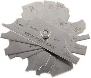
Fillet Weld Gauge

Shown: 7 Piece Fillet Welding Inspection Gauge Set
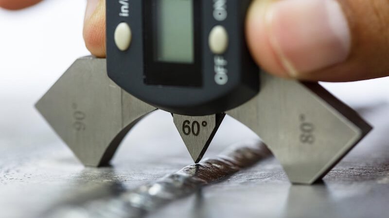
Several pieces of welding equipment are required for visual weld quality testing:
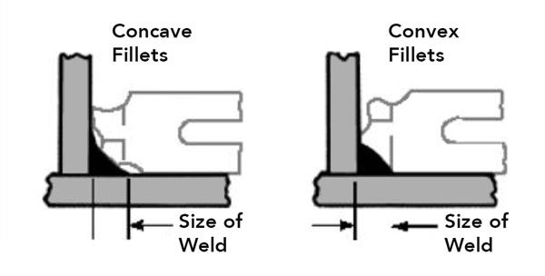
- Weld handheld fillet gauge measures:
- The flatness of the weld
- Convexity (how the weld is welded outward)
- Concavity (how the weld is rounded inward)
- Protective lenses with pocket viewer and shade lens for use when observing the welding process
- A magnifying glass per the code in your area
- Flashlight
- Chisel and/or welding hammer for spatter and slag removal before the weld is inspected
- Temperature device (Tempelstick, Pyrometer) to determine the preheating, interpass and post-heating temperatures.
- Magnet to indicate the type of material being welded
- Tape measure
- Calipers

Related read: Welding Tool List for Beginners
Visual Inspection Before Welding
- Check drawings
- Look at the weld position and how ti corresponds to the specification. Watch the vertical direction of travel
- Check fillet welding symbols
- Does the procedure align with local codes and the weld specification
Weld Material Inspection
- Do the materials purchased match the specification for base metal size and type? Check electrode size, gas selection and grade.
- Check materials for defects. Look for contaminants such as rust, scale, mill, lamination etc.
- Are materials prepared for correct angles
Assembly Inspection
Follow these weld quality testing steps for assembly inspection:
- Check for fit
- Alignment of fixtures and jigs. Check cleanliness (look for spatter from previous jobs)
- Check quality if tack welds are used. The tack weld must be made with the same electrode as the main weld (s).
- Check use of pre heat to slow the cooling rate and to minimize distortion
Equipment Inspection
- Check for damage (cables, ground clamps, electrode holder).
- Check arc voltage
- Check amperage meter for range against specification
Visual Inspection During Welding
- Check electrodes for size, type and storage (low hydrogen electrodes are kept in a stabilizing oven)
- Watch root pass for susceptibility to cracking
- Inspect each weld pass. Look for undercut and required contour. Ensure the weld is cleaned properly between each pass.
- Check for craters that need to be filled
- Check weld sequence and size. Gauges are used to check size.
Inspection After Welding
- Check weld against code and standards
- Check size with gauges and prints
- Check finish and contour
- Check for cracks against standards
- Look for overlap
- Check undercut
- Determine if spatter is at acceptable levels
Gas Weld Testing
Inspection weld quality testing criteria for gas welds:
- The weld should be of consistent width throughout. The two edges should form straight parallel lines.
- The face of the weld should be slightly convex with a reinforcement of not more than 1/16 in. (1.6 mm) above the plate surface. The convexity should be even along the entire length of the weld. It should not be high in one place and low in another.
- The face of the weld should have fine, evenly spaced ripples. It should be free of excessive spatter, scale, and pitting.
- The edges of the weld should be free of undercut or overlap.
- Starts and stops should blend together so that it is difficult where they have taken place.
- The crater at the end of the weld should be filled and show no holes, or cracks.
For Butt Joints:
If the joint is a butt joint, check the backside for complete penetration through the root of the joint. A slight bead should form on the back side.
For Fusion of Lap and T-joint Testing:
The root penetration and fusion of lap and T-joints can be checked by putting pressure on the upper plate until it is bent double. If the weld has not penetrated through the root, the plate will crack open at the joint as it is being bent. If it breaks, observe the extent of the penetration and fusion at the root. It will probably be lacking in fusion and penetration.

Wonderful article Jeff! Simple to read and understand even for a layman in the field of welding.
Incidentally, I got to read this as I was interested in reviewing quality of welds in can making, and am just wondering if the principles are the same in determining weld defects, despite that the technologies might be different?
Yes the principles are the same as all welds should be examined and the factors mentioned should be taken in account. NDT applies to all fields as well.
Can you suggest any NDT equipment that can identify cracks, voids or other defects in an existing weld? Many thanks.
There are a number of options Carol, and a number of questions to answer first in order to properly prescribe the correct method/technique. Feel free to contact me @ [email protected].
Thx
This is a good basic introduction. Regarding NDT there is always more to the story and I advise consulting with a reputable NDT professional. I provide services to a number of entities across various industries and my company has offices across the US. I serve on an ASME Code Committee and will gladly offer advice for the good of the whole.