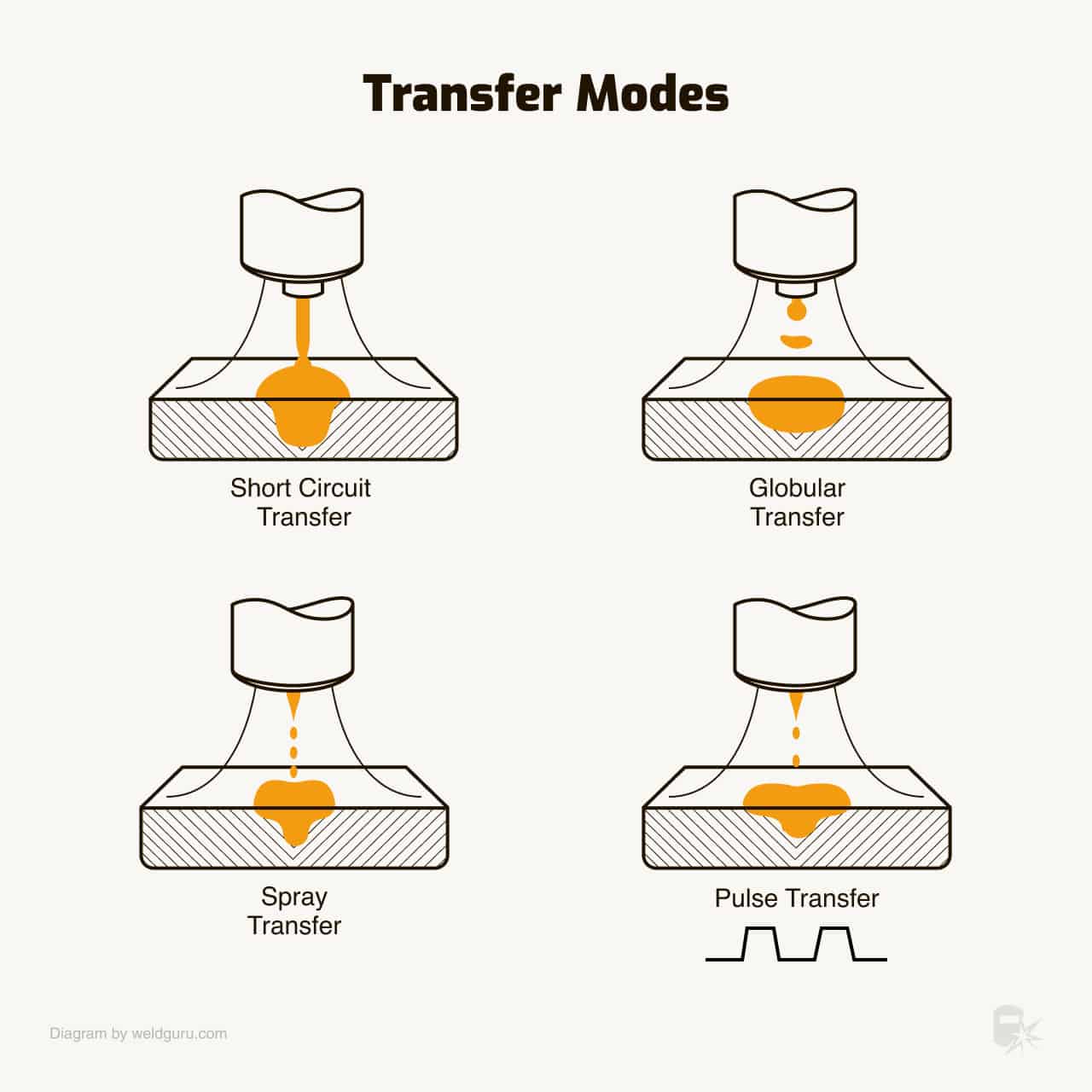
In MIG welding (GMAW), filler metal can be transferred from the electrode to the workpiece in two ways:
- Short-circuiting – This is when the electrode contacts the molten weld pool, thereby establishing a short circuit, which is known as short-circuiting transfer (short-circuiting arc welding);
- Drop transfer (Global or Spray transfer) – This is when discrete drops are moved across the arc gap under the influence of gravity or electromagnetic forces.
Shape, size, the direction of drops (axial or non-axial), and type of transfer are determined by a number of factors.
© weldguru.com – Image usage rights
The factors having the most influence are:
- Magnitude and type of welding current
- Current density
- Electrode composition
- Electrode extension
- Shielding gas
- Power supply characteristics
Axially directed transfer refers to the movement of drops along a line that is a continuation of the longitudinal axis of the electrode.
Nonaxially directed transfer refers to movement in any other direction.
Short Circuiting Transfer
© weldguru.com – Image usage rights
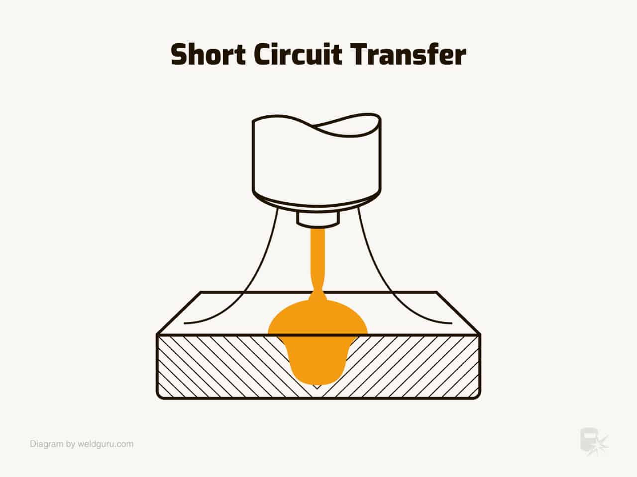
Short-circuiting transfer uses the lowest range of welding currents and electrode diameters associated with MIG welding.
This type of transfer produces a small, fast-freezing weld pool that is generally suited for the joining of thin sections, out-of-position welding, and filling of large root openings.
When weld heat input is extremely low, plate distortion is small. Metal is transferred from the electrode to the workpiece only during a period when the electrode is in contact with the weld pool. There is no metal transfer across the arc gap.
The electrode contacts the molten weld pool at a steady rate in a range of 20 to over 200 times each second. As the wire touches the weld metal, the current increases. It would continue to increase if an arc did not form.
The rate of current increase must be high enough to maintain a molten electrode tip until filler metal is transferred. It should not occur so fast that it causes spatter by the disintegration of the transferring drop of filler metal.
The rate of current increase is controlled by adjustment of the inductance in the power source. The value of inductance required depends on both the electrical resistance of the welding circuit and the temperature range of electrode melting.
The open-circuit voltage of the power source must be low enough so that an arc cannot continue under the existing welding conditions. A portion of the energy for arc maintenance is provided by the inductive storage of energy during the period of short-circuiting.
As metal transfer only occurs during short-circuiting, shielding gas has very little effect on this type of transfer. Spatter can occur, and it is usually caused either by gas evolution or electromagnetic forces on the molten tip of the electrode.
Pros of Short Circuiting Transfer
- Low amperages
- Works on thin materials
- Can be used out of position
Cons of Short Circuiting Transfer
- Can cause spatter
- Can cause cold lap
- Can cause undercut
- Can’t short arc all materials
Globular Transfer
© weldguru.com – Image usage rights
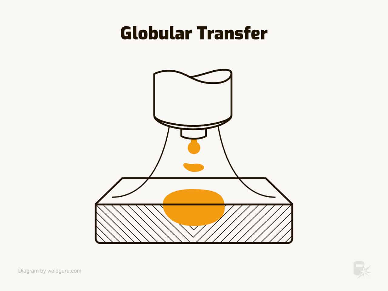
With a positive electrode (DCRP), the globular transfer takes place when the current density is relatively low, regardless of the type of shielding gas. However, carbon dioxide (CO2) shielding yields this type of transfer at all usable welding currents.
The globular transfer method is characterized by a drop size of greater diameter than that of the electrode.
Globular, axially directed transfer can be achieved in a substantially inert gas shield without spatter. The arc length must be long enough to ensure detachment of the drop before it contacts the molten metal. However, the resulting weld is likely to be unacceptable because of lack of fusion, insufficient penetration, and excessive reinforcement.
Carbon dioxide shielding always yields non-axially directed globular transfer. This is due to an electromagnetic repulsive force acting upon the bottom of the molten drops.
The flow of electric current through the electrode generates several forces that act on the molten tip.
The most important of these are pinch force and anode reaction force. The magnitude of the pinch force is a direct function of welding current and wire diameter and is usually responsible for drop detachment.
With CO2 shielding, the wire electrode is melted by the arc heat conducted through the molten drop. The electrode tip is not enveloped by the arc plasma. The molten drop grows until it detaches by short-circuiting or gravity.
Pros of Globular Transfer
- Has a higher deposition rate
- Larger wire
Cons of Globular Transfer
- Can cause spatter
- Can only be used in the flat or horizontal position
Spray Transfer
© weldguru.com – Image usage rights
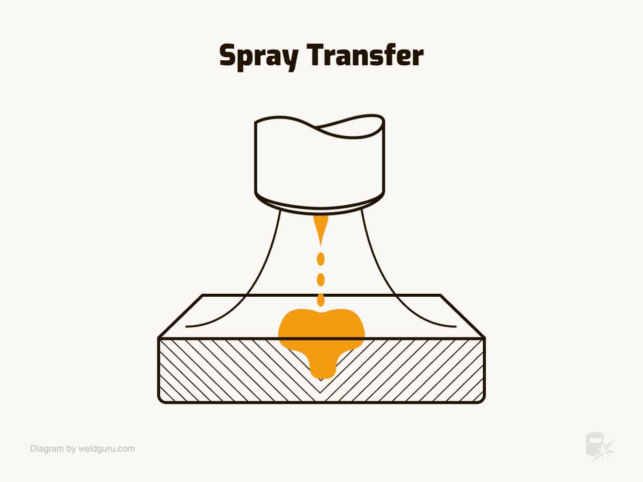
In a gas shield of at least 80 percent argon or helium, filler metal transfer changes from globular to spray type as welding current increases for a given size electrode. For all metals, the change takes place at a current value called the globular-to-spray transition current.
The spray-type transfer has a typical fine arc column and pointed wire tip associated with it. Molten filler metal transfers across the arc as fine droplets. The droplet diameter is equal to or less than the electrode diameter. The metal spray is axially directed.
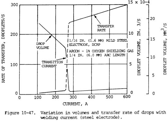
The reduction in droplet size is also accompanied by an increase in the rate of droplet detachment, as illustrated in figure 10-47.
Metal transfer rate may range from less than 100 to several hundred droplets per second as the electrode feed rate increases from approximately 100 to 800 in./min (42 to 339 mm/s).
Pros of Spray Transfer
- No spatter
- Good wash
- Good deposition rate
- Good bead appearance
Cons of Spray Transfer
- Has a very hot arc
- Can only be used in the flat or horizontal position
- Has limited penetration
- Can not weld thin materials
Pulsed Spray Transfer
© weldguru.com – Image usage rights
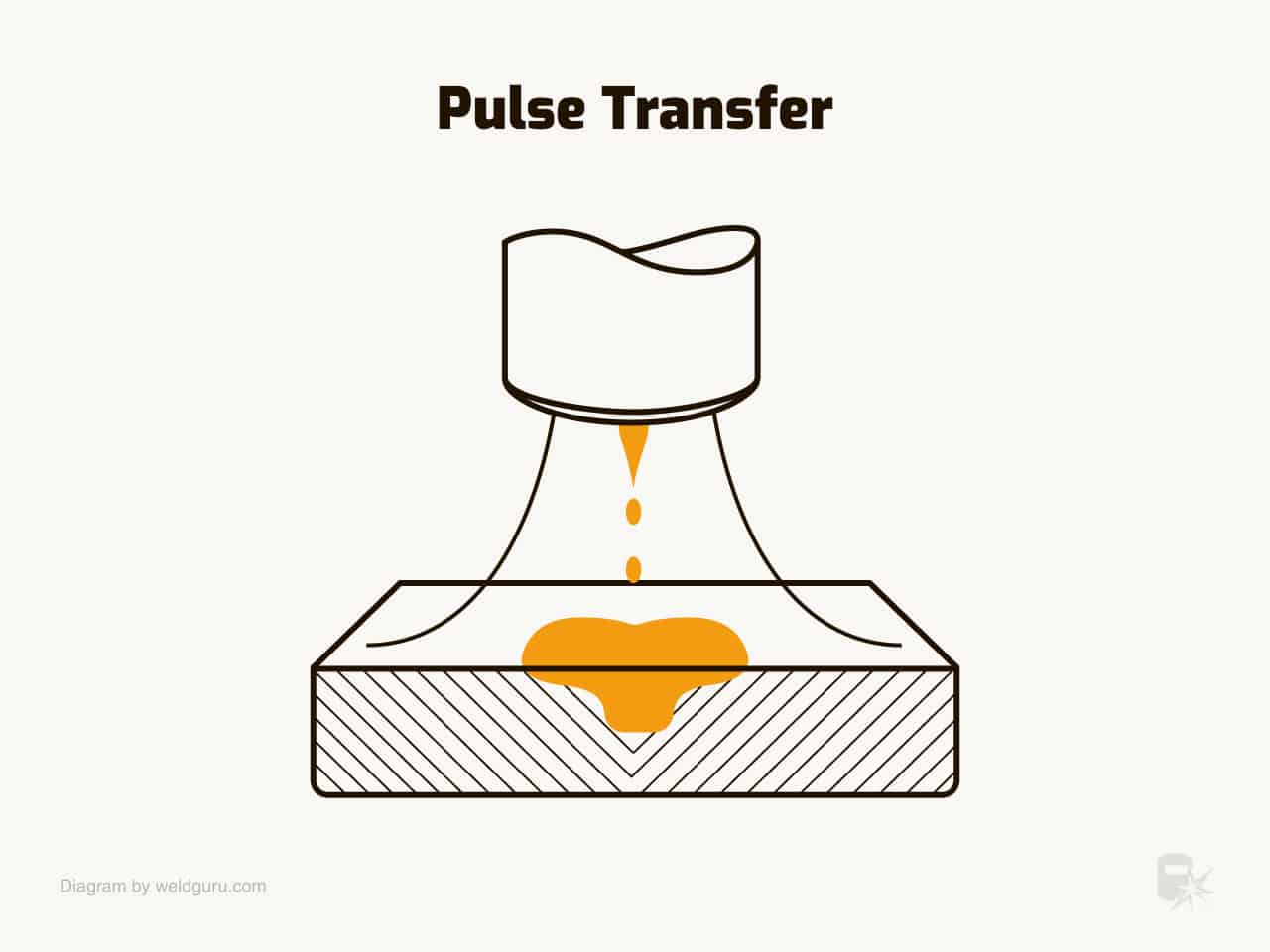
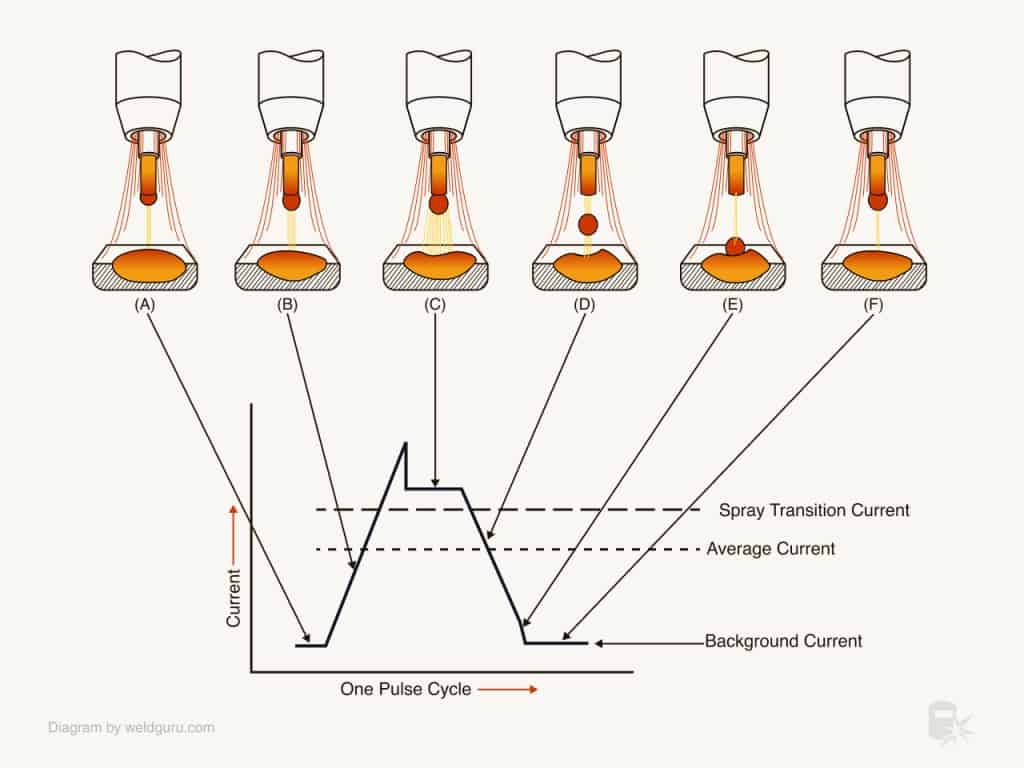
Pulse transfer is a derivative of spray transfer, aiming to maximize its advantages while minimizing its disadvantages. Pulse transfer operates through the cyclical variation of welding current from a high peak current to a low background current.
At the peak current, the high heat input facilitates the detachment of a single droplet from the electrode, which is propelled into the weld pool in a manner similar to spray transfer.
However, unlike continuous spray transfer, pulse transfer allows only a single droplet to form and detach during each pulse.
This is followed by the low background current phase, which maintains the arc but is insufficient to cause metal transfer. The molten droplet at the electrode tip is thus allowed to cool and solidify slightly, ensuring that it does not become too large and detaches prematurely.
© weldguru.com – Image usage rights
This period is critical in reducing the heat input, thereby reducing the potential for burn-through and distortion, particularly in thin materials.
The transition between the peak and background currents occurs rapidly and is controlled by the power source, which must be capable of providing pulse transfer functionality.
The frequency of pulsing can range from a few pulses per second up to several hundred, depending on the welding parameters and requirements.
Pulse transfer also mitigates the limitations of position that affect spray and globular transfers, enabling it to be used in all welding positions.
Furthermore, it offers a high deposition rate, excellent weld bead appearance, and minimizes spatter.
Pulse transfer is especially useful for welding thin or heat-sensitive materials and out-of-position welding, making it a versatile transfer mode.
Read more: Is Pulse MIG Worth It?
Pros Of Pulse Transfer:
- Minimizes heat input, reducing distortion and burn-through
- Can be used in all welding positions
- High deposition rate
- Minimal spatter
- Excellent weld bead appearance
- Effective for thin or heat-sensitive materials
Cons Of Pulse Transfer:
- Requires a specialized power source with pulse capability
- The welding parameters must be precisely controlled, requiring skilled operators
- Potential for lack of fusion if the pulse parameters are not correctly set.
Wrapping it Up
Understanding the characteristics of the various welding transfer modes – short-circuiting, globular, spray, and pulse transfer – is crucial for achieving optimal results in MIG welding.
Each mode has unique pros and cons that make it suitable for certain applications and conditions.
Short-circuiting is ideal for thin materials and out-of-position welding, while globular and spray transfers are efficient but have positional limitations.
Pulse transfer ingeniously combines the benefits of these modes, offering versatility, high deposition rates, and minimal spatter, especially suitable for thin or heat-sensitive materials.
However, it requires precision in parameters and a specialized power source.
Remember, the correct transfer mode can significantly impact the weld’s quality, efficiency, and appearance, necessitating a well-informed choice based on your project.
