The growing DIY movement means a lot more people are welding now.
I think that’s great, but there is one drawback…
There are a lot of people out there with welding machines who don’t have formal training.
That means some people don’t get a few of the fine details welders learn about in school.
One of those details is setting the right parameters on your new MIG welder for the job at hand.
You are probably here for this reason, so I’ll explain the main MIG settings and how they should be adjusted.
Now let’s get that machine set up properly…
Before Setting Your MIG Controls
There’s more to this than grabbing your MIG machine and twisting the dials.
Your MIG settings, like those of any welding process, depend heavily on the job you’re approaching.
There’s no generic assortment of settings that always applies. Welding is a custom craft, and it depends on a lot of variables.
What’s Your Material?
Different materials have different characteristics related to heat and electricity. It matters a great deal what material you’re welding. The characteristics of mild steel are very different from those of aluminum.
Aluminum doesn’t melt at the same temperature as mild steel nor conducts electricity or holds heat to the same degree as stainless steel or titanium.
Before you can even start, you have to choose the right process and take care of the mechanical and technical setup. The wire you choose, the shielding gas, and the machine settings all depend on the material.
Mild steel, aluminum, and stainless or nickel alloys are the most used metals with the MIG process. They are the main metal found around the home and in cars.
Related: MIG Welding Stainless Steel Explained
How Thick is the Metal?
Know the thickness of the metal so you know if your welder has the power to get the job done, you can choose the right electrode wire and the proper shielding gas.
You can make plans for how you approach your project concerning clamping, angle of approach, cooling, dealing with your welder’s duty cycle, and other practical solutions.
You set the amperage according to the thickness of the metal. Therefore, you have to know how thick your metal is.
A general rule of thumb is you need 1 amp of power for every 0.001 inches of steel.
Stainless needs 10-15 percent less current, and aluminum needs around 25 percent more.
So, how many amps does it take to weld 3/8 steel?
For 1/8-inch mild steel, which is 0.125-inch thick, 125 amps would be a good place to start.
3/8-inch thickness is 0.375 (3 x 0.125), so do you really need 375 amps for this? Some welding machines claim to weld 3/8-inch steel with only 170-200 amps. How is that possible?
First, these numbers are estimates. They only put you in the ballpark.
Second, manufacturers indulge in a little bit of magic to get these numbers to advertise performance. They bevel the edges of the joint to get the thickness down. This way, less current can make the same weld in one pass.
Shielding Gas and Electrode Wire
For good results, it’s necessary to use the right shielding gas and electrode. These choices are heavily influenced by material composition and thickness.
Some wire and gas combinations commonly seen with MIG welding are:
- Mild/carbon steel – ER70s wire and 75/25 percent ratio of Argon to CO2
- Stainless – ER308L wire and 98 percent Argon with 2 percent CO2
- Aluminum – ER4043 wire and 100% Argon shielding
You choose your wire size by the amperage setting, which in turn depends on material thickness. Here are the most-used wire sizes in MIG welding.
Notice that these sizes overlap through each current range. This gives you some choice about what works best for your welder and your technique.
- 0.023 – 30-130 amps
- 0.030 – 40-145 amps
- 0.035 – 50-180 amps
- 0.045 – 75-250 amps
Equipment Considerations
Quality welding equipment makes things easier. For instance, to weld aluminum with a MIG welder, installing a spool gun for trouble-free wire feeding is better. Make sure your bottle of shielding gas is full, and the hookups are clean and tight.
Some MIG welders automate most of the settings process which makes it easier to set up.
Onboard digital menus and input variables like material type and thickness, will set the MIG welder up automatically.
You’ll still need to load the right wire and gas, but some of the tricky settings are handled for you.
Check out our MIG Welders Guide for information about some of these machines.
Prepare Your Workpiece
To get great welding results that are repeatable your metal needs to ready to work on.
Preparation metal work includes:
- cleaning
- de-scaling
- grinding
- degreasing
- clamping
Settings don’t create good welds; they just make good welds possible. But only if you do the rest.
Three things to remember about joint prep:
- Clean joint, clean bead
- Settings for dirty metal don’t apply to clean metal
- Less oil or paint to catch fire means less to think about
MIG Welding Settings for Mild Steel
Now… let’s make some settings…
For simplicity’s sake, I’m going to stick with settings for mild steel for the most part because it’s by far the most-welded metal on the planet.
I’ll mention aluminum or other materials whenever they’re relevant.
Which MIG Settings Matter Most?
Although your welder may have a nice selection of adjustments, it’s important to understand that most of them are for fine-tuning.
Three basic settings define the rest. These basic settings are:
- Voltage level
- Wire feed speed (WFS)
- Shielding gas type and rate
You want to create the right heat conditions at the weld to run a smooth arc, eliminate spatter and maximize penetration.
These settings also determine the transfer type for metal deposition. Read more about MIG transfer types here.
1. Voltage Level
The MIG power source is a Constant Voltage system. Once it’s set at a given level, voltage won’t deviate much. Voltage determines arc length as well as the height and width of the bead.
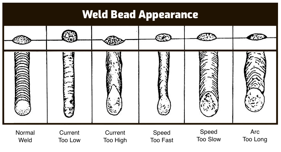
Voltage fine-tuning is a trial and error process. It’s checked by inspecting the bead for deficiencies. I’ve included a chart below to help you select your voltage by inspecting the bead.
2. Wire Feed Speed
Wire feed speed (WFS) affects your heat level. It’s measured in inches per minute (IPM). If the feed rate is low, the weld area can run too cool for good penetration.
Higher feed rates allow better contact between the wire and weld puddle. Increasing the current level and creating too much heat results in spattering.
Voltage level and feed rate need to be balanced against each other.
If the sparks are flying all over and you have spatter the size of the welding wire or larger, you have one of two situations:
- Too much WFS for the voltage setting
- Too little voltage for the WFS setting.
If the arc burns back up inside the tip, you have one of two situations:
- Too much voltage for the WFS setting
- Foo little WFS for the voltage setting.”
There’s one more critical factor to your wire feed speed: The distance the electrode wire protrudes from the contact tip of the MIG gun.
This distance is called Electrode Stickout (ESO), and it’s a limiting factor. You need to maintain a consistent distance above the work while welding, or you can’t get consistent results from your settings. Form the habit of frequently checking your ESO distance.
3. Gas Type and Rate
The flow rate, volume, and type of shielding gas determine transfer type when combined with voltage and wire speed.
Higher concentrations of helium or argon make for a hotter arc. The whole point of shielding gas is to shield the arc and weld puddle from oxygen. The nature of pressurized gas flow means experimenting and analyzing. In other words, trial and error.
Related read: MIG Welding Gas Pressure Setting
Gas is metered in cubic feet per minute (CFM), and drafts, breezes, or cylinder temperatures affect the results.
Maybe when things are still, 5 CFM is enough to shield the weld properly. But leave a door open, and a draft may blow the gas away at that rate, so you need to go to 35 CFM, for example.
However, if there’s too much gas pressure at the weld, you can draw oxygen into the arc plasma and contaminate the bead, causing porosity.
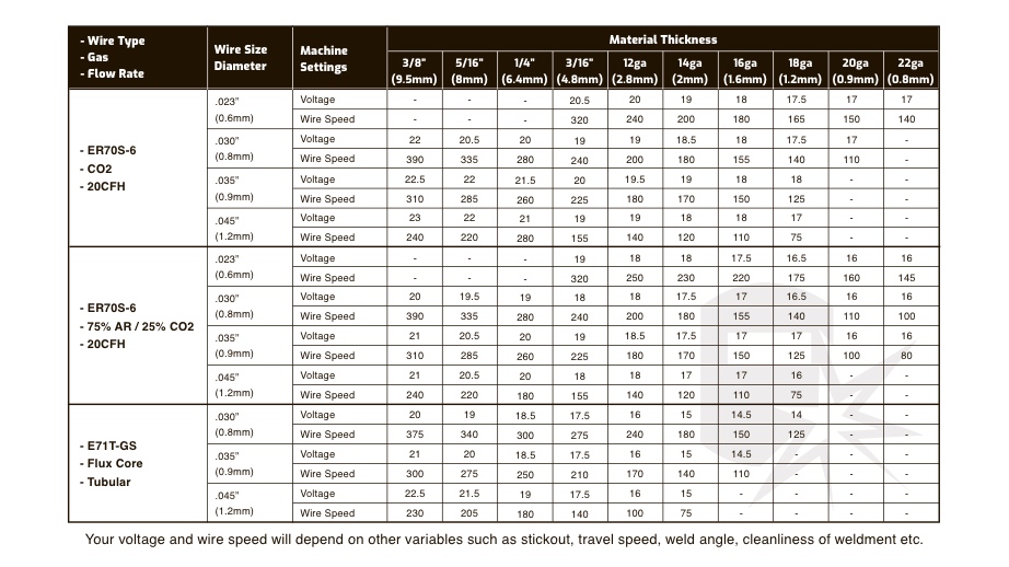
MIG Welding Settings Chart – Wire Speed & Voltage

There are many MIG setting charts available from manufacturers that all vary.
Here’s a settings chart I put together that is a general guide to get you started – remember this is just a guide.
Always test your settings on a scrap piece of metal. You may need to dial them in, depending on your setup.
What The Weld Bead Tells You About Your MIG Settings

Another way to check your MIG settings is to inspect the weld bead. It will tell you what it needs. You just have to pay attention…
- Normal bead: Good penetration into the base, flat profile, appropriate width, and ties in well at the ends.
- Amps set too low: Narrow, possibly convex bead with poor tie-in at the ends.
- Amps too high: Poor arc starts, excessively wide bead, burn-through, a lot of spatter, and poor penetration.
- Traveling too fast: Moving too fast with your arc hand yields a narrow, convex bead, inadequate tie-in at the ends, poor penetration, and inconsistent bead.
- Traveling too slow: Going too slowly adds too much heat giving a bead that’s too wide and poor penetration.
- Arc too long: Caused by too much voltage. Long, skinny arc, bad penetration, and weld puddle turbulence.
- No shielding gas: A lack of shielding gas causes porosity and pinholes in the bead.
Still struggling with your MIG welds? Read these MIG welding tips & tricks.
Now You Know
It may be a disappointment to some, finding out there’s no quick, easy answer to the questions you’re grappling with. When it comes to welding, it’s the nature of the game, I’m afraid.
Take this information and these charts not as gospel nor as science. This is simply a place to start. The rest of your craft is up to you. These are only guidelines. Watch your weld puddle and inspect your beads.
You’ve involved yourself in a craft. By its very nature, handcrafting isn’t scientific. It’s a challenge, and most times, the only reward is quiet victory over your latest bad habit.

I applied your recommended settings to my MIG.
I can finally make long passes on 18ga consistently without holes and spatter.
Thank You Sir!
Hi Jeff, Not sure if you still maintain this or not but just wanted to let you know I found your information extremely helpfull. I recently purchased a very nice welder that does mma, lift tig, mig and flux core and the only thing is are the settings are in amps not voltage so it is synergic but you set the amps to the metal size, it sets the voltage and only displays the amps lol. The dial for volts is there and it adjusts – and + 1.5 v but again the screen just shows amps and that 120 amps or what ever you have it set for does not change when moving the micro adjust on volts. It is what it is. It makes very good welds on 110v c-25 but is set for c-20 not c-25 and also has a setting for c02 but I couldnt get my c02 bottle exchanged here.. Thanks for the explanations, they helped alot.
I concur with Steve above. Having dug out my Wolf 140 and finally decided to learn to weld halfway properly, I’ve been all over the net and TimWelds on YouTube and this page have been the most informative.
Hi Jeff ~ I see that the last update was on July 8, 2022, so seeing that it’s only 5 days later, I assume that you’re maintaining this article. Bearing this in mind, I’d appreciate it if you would fix the link that’s mentioned below the “MIG Welding Settings Chart – Wire Speed & Voltage” chart. Specifically, the link that’s supposed to allow the reader to print a full-size chart that can actually be used. I’ve already copied and pasted the one show herein, but, after its been expanded to 8.5 x 11 size, it’s no longer legible. Thank you for the useful article and please keep up the fine work.
Thanks for spotting that Rob, the link was missing – just added it back in.
Much obliged, Jeff. The link is providing a nice high-resolution chart now.