Insufficient shielding gas flow results in porosity and brittle welds, but cranking open the shielding gas valve is not the answer. You can make things worse by using a shielding gas flow that is too high.
So, the solution is to find that sweet spot and stay between the two extremes.
Typically, if you’re welding mild steel and you are welding indoors using pure CO2 or a 75/25 Ar/CO2 mix, a good gas pressure range for MIG welding is 10-15 CFH. But, if you notice any porosity, increase it to the recommended flow rate of 20-30 CFH.
However, that’s just one scenario…
This article will teach you how to properly adjust the gas flow rate, the minimum and maximum values, and the best shielding gas settings for common materials welding using the MIG process.
Related read: Overview of the GMAW Process
Best MIG Gas Flow Rates
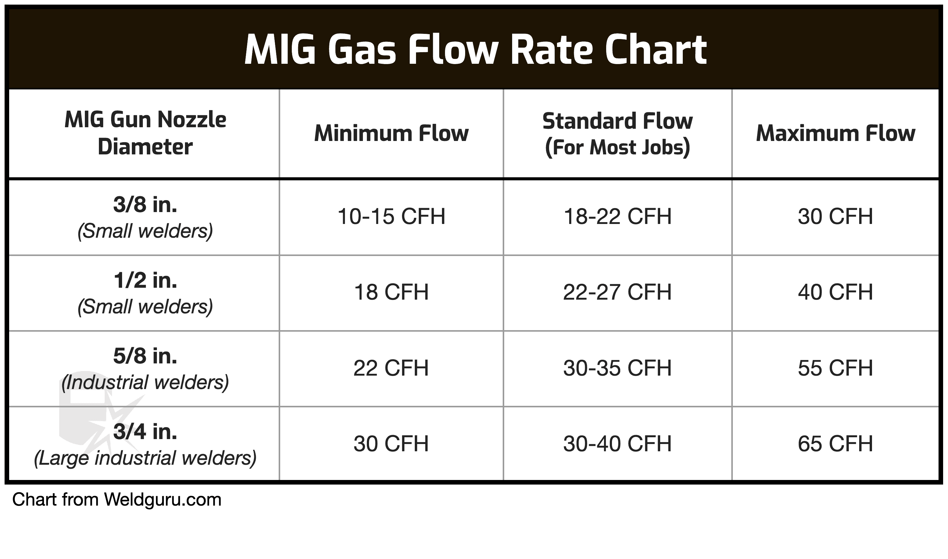
The chart below shows minimum and maximum gas flow rates for standard MIG nozzle diameters for argon mixtures and CO2.

© weldguru.com – Image usage rights
The most common metals welded with the MIG process include mild steel, stainless steel, and aluminum.
Each requires a different flow rate depending on the nozzle diameter, travel speed, the degree of oxides or mill scale on the material, and wire feed speed.
So, let’s discuss how the shielding gas flow impacts welding these materials.
Steel
Mild steel is relatively easy to weld. If you are welding indoors using pure CO2 or a 75/25 Ar/CO2 mix, you will be fine with just 10-15 CFH. But, if you notice any porosity, increase it to the recommended flow rate of 20-30 CFH.
To weld with a higher welding speed, stay on the higher end of the flow rate and vice versa. Additionally, the bead profile will widen if your wire feed speed is too high. A wide bead also requires a higher shielding gas flow to cover the molten material entirely.
If you use a nozzle diameter larger than 1/2 in., the correct shielding gas range is between 22 CFH and 55 CFH. But, most small welding machines use MIG gun nozzles with a 1/2 in. diameter or smaller.
Stainless Steel
Stainless steel is a far more complex metal to weld. Tens of variables impact the resulting weld quality, from the stainless steel type to your heat management. So not surprisingly, shielding gas flow can also affect the weld quality.
A good starting point is 20 to 25 CFH. Keep an eye on the weld surface and the area around weld toes. If you notice porosity, increase the flow.
Using a tri-mix shielding gas (i.e., 10% Ar + 85-90% He + 2-5% CO2) increases the amount of helium when you increase the gas flow rate. Since helium conducts heat rapidly and stainless steel doesn’t, you may create concentrated heat spots unless you manage your heat input carefully.
So, too much helium and poor heat management can lead to carbide precipitation and warping on thin sheet metal.
On the other hand, since helium is lighter than argon or CO2, if you don’t use a high enough flow rate, too little helium will be present, and the metal will experience porosity. So, it does take a bit of tweaking to get proper shielding gas coverage with your particular MIG welder.
Read more: MIG Welding Stainless Steel – A Beginners Guide
Aluminum
Aluminum conducts heat very efficiently. So to MIG weld aluminum, you must employ high travel speeds. As a result, this requires a higher shielding gas flow of around 30 CFH.
To MIG weld aluminum, you must use a completely inert gas. Pure argon is the best choice for most jobs. But, to weld thick aluminum, helium may be added to the argon.
Helium improves heat transfer and penetration. However, since helium is much lighter than argon, you may need to significantly increase the shielding gas flow rate depending on the included helium percentage.
For example, using 75% helium and 25% argon may require a flow rate as high as 50 CFH.
How to Adjust the Gas Flow Rate
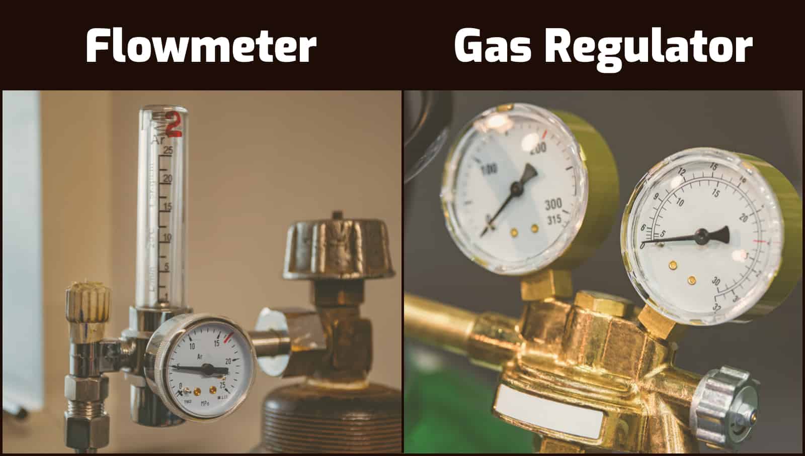
Adjusting the shielding gas flow rate is relatively straightforward. Every gas regulator has a single valve that lets you modify the flow rate. Standard gas regulators have two gauges.
One shows the pressure in the gas bottle measured in PSI, and another displays the gas flow rate in cubic feet per hour (“CFH”). You release gas from the bottle by opening the valve, and the gauge’s needle moves accordingly to show the gas flow rate in CFH.
However, higher-quality gas regulators with a flow meter have only one gauge that displays the gas bottle pressure. Then instead of a second gauge, the outbound gas flow rate is indicated using a specially designed vertical plastic chamber.

© weldguru.com – Image usage rights
The transparent chamber has inscribed measurements in CFH and a small metal ball on the inside. The gas flows through this chamber, and the pressure makes the ball rise. That’s why they are referred to as “flow meter regulators.”
Like with the standard regulators, you increase the gas flow rate by opening the valve. But, having the additional verification that the ball floats at a certain level is much more reliable.
There is nothing wrong with typical regulators. However, the needle and springs inside the gas flow regulator may get stuck, or its mechanical function may diminish.
But, flow meter regulators rely on gravity and gas pressure to display the flow rate, and this measurement is devoid of the mechanics found in regulators.
Essentially, the flow meter design relies on basic physics and a simple design, not the complicated mechanics of a needle inside a pressure gauge.
CFH or Liters Per Minute?
Cubic feet per hour is the preferred unit to measure gas flow rate. However, some welding gas regulators measure liters per minute (“l/min”).
We don’t recommend such regulators because most literature and welding guides provide CFH guidelines.
Is Every Gas Measured Equally?
No. Some shielding gasses are denser and heavier than others. That’s why you must match the regulator and the shielding gas.
For example, if the regulator is calibrated for argon-only, you will get an inaccurate reading if you attach it to the helium shielding gas bottle.
It is not much of an issue when MIG welding because CO2 and argon are not that different. However, keep in mind that you need a regulator designed for your gas to get accurate flow rate readings.
Pure CO2 Tanks Require Special Regulators
If you wish to use a gas regulator or a flow meter with a 100% CO2 gas tank, keep in mind that it may freeze because of the low CO2 temperature created as this gas expands. It’s best if you use a regulator rated for CO2.
Most people never experience a total regulator freeze. But with prolonged use, you will see some frost build up on the regulator. Additionally, CO2 gas tanks use a CGA-320 connector, while all other welding gas bottles use CGA-580.
Every argon/CO2 regulator is threaded for CGA-580. So, to use any gas regulator with a CO2 gas bottle, you need this CGA-320 to CGA-580 adapter.
Is There a Minimum Gas Flow Rate?
The minimum shielding gas flow rate depends on the welded material and the air dynamics around you.
For aluminum, you shouldn’t use anything below 20 CFH. But when welding mild steel, you can work well with a shielding gas flow as low as 10 CFH.
It’s important to use a higher flow rate if welding outside. But, if you shield the joint appropriately with stands, you can reduce the required shielding gas flow rate.
As a rule of thumb, you should never use a gas flow rate lower than 10-15 CFH. Of course, this doesn’t mean your welds won’t develop porosity with such a low flow rate.
For example, if the joint is wide and your travel speed and wire feeding speed are high, the weld may become porous due to insufficient shielding gas coverage.
Is There a Maximum Gas Flow Rate?
There is a maximum shielding gas flow rate because the overly strong flow can create turbulence and fail to protect the molten metal from atmospheric contamination.
Thanks to the venturi effect, the surrounding air around the nozzle’s edge gets sucked into the shielding gas envelope if the flow rate is too high. So, the maximum flow rate depends on the MIG nozzle size.
Air is highly detrimental to weld quality, so we use the shielding gas to protect the weld pool. But the shielding gas loses its protective role once air mixes with it. Entrapped pockets of air cause porosity and weld brittleness.
Summary Chart
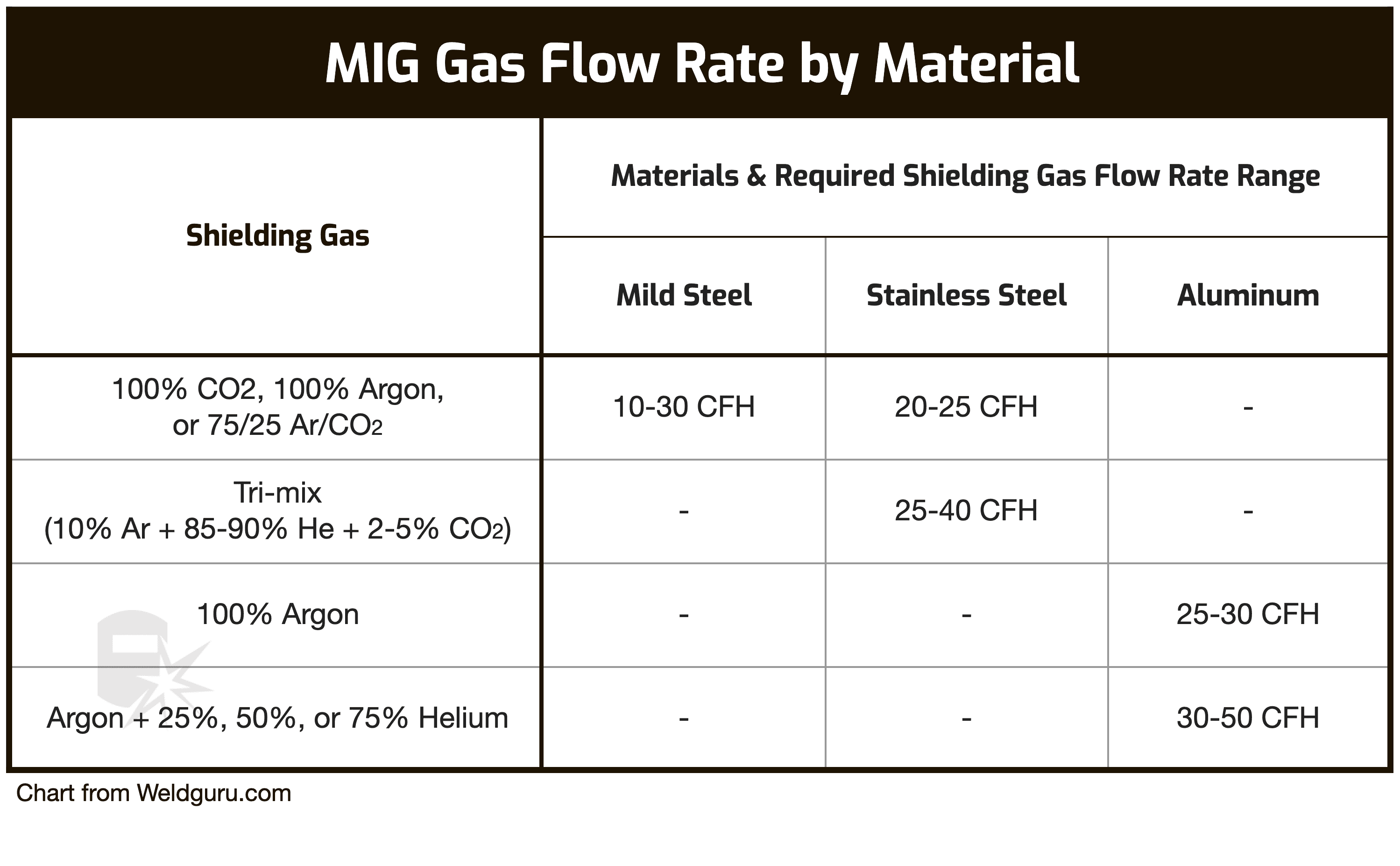
The table below summarizes the information we discussed so far to help you set the shielding gas flow rate depending on the welded material.
Note that the chart provides estimates. The best flow rate for your welder depends on joint configuration, welding position, travel speed, wire feeding speed, and material thickness.

© weldguru.com – Image usage rights
Wrapping It
Finding the sweet spot is the trick to achieving sufficient shielding gas coverage. You cannot use too low or too high gas flows as both scenarios create problems.
We provided some recommendations for starting points, but you will need to practice and tweak your flow rate for your machine and technique.
It’s most economical to use the least amount of gas possible. So, don’t force a higher flow rate because the weld doesn’t benefit from it.
Even if your rate is too low to cause turbulence, you waste costly gas if the rate is too high. Reduce the flow rate whenever possible and only use as much gas as needed.
If you have some unanswered questions, read my article on MIG welder settings that explains how to set up your machine correctly.
Lastly, check out these MIG welding tips and tricks for beginners to help improve your welds.
