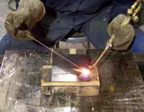
Oxy-Fuel welding (OFW) is a group of welding processes that join metals by heating them with a fuel gas flame or flares with or without the application of pressure and with or without the use of filler metal.
Oxy Fuel welding includes any welding operation that makes use of a fuel gas combined with oxygen as a heating medium.
The process involves the melting of the base metal and a filler metal if used, by means of the flame produced at the tip of a welding torch.
Oxy Fuel welding fuel gas and oxygen are mixed in the proper proportions in a mixing chamber which may be part of the welding tip assembly.
Molten metal from the plate edges and filler metal, if used, intermix in a common molten pool. Upon cooling, they coalesce to form a continuous piece.
OFW Processes
There are three major processes within the OFW group:
- oxyacetylene welding
- oxyhydrogen welding,
- pressure gas welding.
There is one process of minor OFW industrial significance, known as air acetylene welding, in which heat is obtained from the combustion of acetylene with air.
Welding with methylacetone-propadiene gas (MAPP gas) is also an oxyfuel procedure.
Advantages
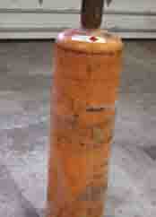
There are three key advantages of OFW welding:
- Control of heat – One advantage of this welding process is the control a welder can exercise over the rate of heat input, the temperature of the weld zone, and the oxidizing or reducing potential of the welding atmosphere.
- Control of weld bead – The size, shape and weld puddle viscosity are also controlled in the welding process because the filler metal is added independently of the welding heat source.
- OFW welding is ideally suited to the welding of thin sheet, tubes, and small diameter pipe. It is also used for repair welding. Thick section welds, except for repair work, are not economical.
Equipment and Kits
The equipment used in Oxy-Fuel welding is low in cost, usually portable, and versatile enough to be used for a variety of related operations, such as bending and straightening, preheating, post heating, surface, braze welding, and torch brazing.
With relatively simple changes in equipment, manual and mechanized oxygen cutting operations can be performed. Metals normally welded with the oxyfuel process include steels, especially low alloy steels, and most nonferrous metals. The process is generally not used for welding refractory or reactive metals.
See the best oxy-fuel cutting torch kits here.
Oxy Fuel Gases
Commercial fuel gases have one common property: they all require oxygen to support combustion. To be suitable for welding operations, a fuel gas, when burned with oxygen, must have the following:
- High flame temperature.
- High rate of flame propagation.
- Adequate heat content.
- Minimum chemical reaction of the flame with base and filler metals.
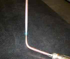
Among the many reasons why welders use Oxy-acetylene gas flames (OFW), is the high operating temperatures (5,589 degrees Fahrenheit) and the ability to melt many common metals.
Among the commercially available OFW, Oxy Fuel welding fuel gases, acetylene (a combination of hydrogen and carbon) most closely meets all these requirements.
Other gases, fuel such as MAPP gas, propylene, propane, natural gas, and proprietary gases based on these, have sufficiently high flame temperatures but exhibit low flame propagation rates.
These OFW welding gas flames are excessively oxidizing at oxygen-to-fuel gas ratios high enough to produce usable heat transfer rates. Flame holding devices, such as counterbores on the tips, are necessary for stable operation and good heat transfer, even at the higher ratios.
These OFW welding gases, however, are used for oxygen cutting. They are also used for torch brazing, soldering, and many other operations where the demands upon the flame characteristics and heat transfer rates are not the same as those for welding.
Types of Flames
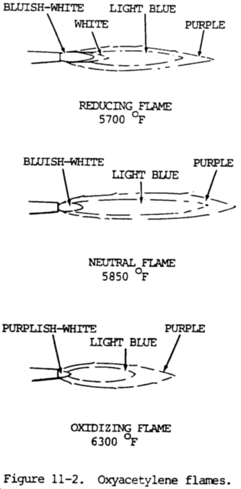
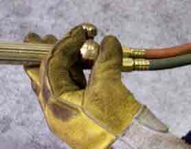
Three types of welding flames can be created with oxy-acetylene (OFW). Each one can be differentiated by the color, size and shape. Each flame can be created with a unique mixture of acetylene and oxygen.
- Carburizing: uses a mix of more acetylene compared to oxygen. Used for soldering, welding, braze welding and silver brazing.
- Neutral: most common type. It is created with a balanced mix of oxygen and acetylene. Causes a slow melt. It creates fewer sparks and does not boil. It protects steel from oxidation and the joint does not burn. It results in strong welds.
- Oxidizing: as the name implies, uses a richer mix of oxygen than acetelyne. This type of flame isn’t considered to be practical for welding. It can causes issues such as hardening at the weld, weld weakness and brittleness.
Base Metal Preparation
Dirt, oil, and oxides can cause incomplete fusion, slag inclusions, and porosity in the weld. Contaminants must be removed along the joint and sides of the base metal.
The root opening for a given thickness of metal should permit the gap to be bridged without difficulty, yet it should be large enough to permit full penetration. Specifications for root openings should be followed exactly.
The thickness of the base metal at the joint determines the type of edge preparation for welding. Thin sheet metal is easily melted completely by the flame. Thus, edges with square faces can be butted-together and welded.
This type of joint is limited to material under 3/16 in. (4.8 mm) in thickness. For thicknesses of 3/16 to 1/4 in. (4.8 to 6.4 mm), a slight root opening or groove is necessary for complete penetration, but filler metal must be added to compensate for the opening.
Joint edges 1/4 in. (6.4 mm) and thicker should be beveled. Beveled edges at the joint provide a groove for better penetration and fusion at the sides.
The angle of bevel for oxyacetylene welding varies from 35 to 45 degrees, which is equivalent to a variation in the included angle of the joint from 70 to 90 degrees, depending upon the application.
A root face 1/16 in. (1.6 mm) wide is normal, but feather edges are sometimes used. Plate thicknesses 3/4 in. (19 mm) and above are double beveled when welding can be done from both sides. The root face can vary from 0 to 1/8 in. (0 to 3.2 mm).
Beveling both sides reduces the amount of filler metal required by approximately one-half. Gas consumption per unit length of weld is also reduced.
A square groove edge preparation is the easiest to obtain. This edge can be machined, chipped, ground, or oxygen cut. The thin oxide coating on oxygen-cut surface does not have to be removed, because it is not detrimental to the welding operation or to the quality of the joint. A bevel angle can be oxygen cut.
Multiple Layer Welding
Multiple layer welding is used when maximum ductility of a steel weld in the as-welded or stress-relieved condition is desired, or when several layers are required in welding thick metal.
Multiple layer welding is done by depositing filler metal in successive passes along the joint until it is filled. Since the area covered with each pass is small, the weld puddle is reduced in size.
This procedure enables the welder to obtain complete joint penetration without excessive penetration and overheating while the first few passes are being deposited. The smaller puddle is more easily controlled. The welder can avoid oxides, slag inclusions, and incomplete fusion with the base metal.
Grain refinement in the underlying passes as they are reheated increases ductility in the deposited steel. The final layer will not have this refinement unless an extra pass is added and removed or the torch is passed over the joint to bring the last deposit up to normalizing temperature.
Weld Quality
The appearance of a weld does not necessarily indicate its quality. Visual examination of the underside of a weld will determine whether there is complete penetration or whether there are excessive globules of metal.
Inadequate joint penetration may be due to insufficient beveling of the edges, too wide a root face, too great a welding speed, or poor torch and welding rod manipulation.
Over-sized and undersized welds can be observed readily. Weld gauges are available to determine whether a weld has excessive or insufficient reinforcement. Undercut or overlap at the sides of the welds can usually be detected by visual inspection.
Although other discontinuities, such as incomplete fusion, porosity, and cracking may or may not be apparent, excessive grain growth or the presence of hard spots cannot be determined visually.
Incomplete fusion may be caused by insufficient heating of the base metal, too rapid travel, or gas or dirt inclusions. Porosity is a result of entrapped gases, usually carbon monoxide, which may be avoided by more careful flame manipulation and adequate fluxing where needed. Hard spots and cracking are a result of metallurgical characteristics of the weldment.
Working Pressures for Welding Operations
The required OFW working pressure increases as the tip orifice increases. The relation between the tip number and the diameter of the orifice may vary with different manufacturers. However, the smaller number always indicates the smaller diameter. For the approximate relation between the tip number and the required oxygen and acetylene pressures, see tables 11-1 and 11-2.
Oxyfuel Welding Rods
The welding rod, which is melted into the welded joint, plays an important part in the quality of the finished weld. Good welding rods are designed to permit free flowing metal which will unite readily with the base metal to produce sound, clean welds of the correct composition.
Welding rods are made for various types of carbon steel, aluminum, bronze, stainless steel, and other metals for hard surfacing.
Oxyfuel Welding Fluxes
Oxides of all ordinary commercial metals have higher melting points than the metals and alloys (except steel) have themselves. They are usually pasty when the metal is quite fluid and at the proper welding temperature.
An efficient flux will combine with oxides to form a fusible slag. The slag will have a melting point lower than the metal so it will flow away from the immediate field of action. It combines with base metal oxides and removes them. It also maintains cleanliness of the base metal at the welding area and helps remove the oxide film on the surface of the metal.
The welding area should be cleaned by any method. The flux also serves as a protection for the molten metal against atmospheric oxidation.
The chemical characteristics and melting points of the oxides of different metals vary greatly. There is no one flux that is satisfactory for all metals, and there is no national standard for gas welding fluxes. They are categorized according to the basic ingredient in the flux or base metal for which they are to be used.
Fluxes are usually in powder form. These fluxes are often applied by sticking the hot filler metal rod in the flux. Sufficient flux will adhere to the rod to provide proper fluxing action as the filler rod is melted in the flame.
Other types of fluxes are of a paste consistency which are usually painted on the filler rod or on the work to be welded.
Welding rods with a covering of flux are also available. Fluxes are available from welding supply companies and should be used in accordance with the directions accompanying them.
The melting point of a flux must be lower than that of either the metal or the oxides formed so that it will be liquid. The ideal flux has exactly the right fluidity when the welding temperature has been reached. The flux will protect the molten metal from atmospheric oxidation. Such a flux will remain close to the weld area instead of flowing all over the base metal for some distance from the weld.
Fluxes differ in their composition according to the metals with which they are to be used. In cast iron welding, a slag forms on the surface of the puddle. The flux serves to break this up. Equal parts of carbonate of soda and bicarbonate of soda make a good compound for this purpose. Nonferrous metals usually require a flux.
Copper also requires a filler rod containing enough phosphorous to produce a metal-free from oxides. Borax which has been melted and powdered is often used as a flux with copper alloys.
A good flux is required with aluminum because there is a tendency for the heavy slag formed to mix with the melted aluminum and weaken the weld. For sheet aluminum welding, it is customary to dissolve the flux in water and apply it to the rod. After welding aluminum, all traces of the flux should be removed.
Cutting
If iron or steel is heated to its kindling temperature (not less than 1600ºF (871ºC)), and is then brought into contact with oxygen, it burns or oxidizes very rapidly.
The reaction of oxygen with iron or steel forms iron oxide (Fe3O4) and gives off considerable heat. This heat is sufficient to melt the oxide and some of the base metal; consequently, more of the metal is exposed to the oxygen stream. This reaction of oxygen and iron is used in the oxyacetylene-cutting process. A stream of oxygen is firmly fixed onto the metal surface after it has been heated to the kindling temperature. The hot metal reacts with oxygen, generating more heat and melting. The molten metal and oxide are swept away by the rapidly moving stream of oxygen. The oxidation reaction continues and furnishes heat for melting another layer of metal. The cut progresses in this manner.
Theoretically, the heat created by the burning iron would be sufficient to heat adjacent iron red hot, so that once started the cut could be continued indefinitely with oxygen only, as is done with the oxygen lance. In practice, however, excessive heat absorption at the surface caused by dirt, scale, or other substances, make it necessary to keep the preheating flames of the torch burning throughout the operation.
Cutting Steel and Cast Iron
General. Plain carbon steels with a carbon content not exceeding 0.25 percent can be cut without special precautions other than those required to obtain cuts of good quality. Certain steel alloys develop high resistance to the action of the cutting oxygen, making it difficult and sometimes impossible to propagate the cut without the use of special techniques. These techniques are described briefly in (2) and (3) which follow:
High carbon steels. The action of the cutting torch on these metals is similar to a flame-hardening procedure, in that the metal adjacent to the cutting area is hardened by being heated above its critical temperature by the torch and quenched by the adjacent mass of cold metal. This condition can be minimized or overcome by preheating the part from 500 to 600ºF (260 to 316ºC) before the cut is made.
Waster Plate on Alloy Steel
The cutting action on an alloy steel that is difficult to cut can be improved by clamping a mild steel “waster plate” tightly to the upper surface and cutting through both thicknesses. This waster plate method will cause a noticeable improvement in the cutting action, because the molten steel dilutes or reduces the alloying content of the base metal.
Chromium and Stainless steels
These and other alloy steels that previously could only be cut by a melting action can now be cut by rapid oxidation through the introduction of iron powder or a special nonmetallic powdered flux into the cutting oxygen stream. This iron powder oxidizes quickly and liberates a large quantity of heat. This high heat melts the refractory oxides which normally protect the alloy steel from the action of oxygen. These molten oxides are flushed from the cutting face by the oxygen blast. Cutting oxygen is enabled to continue its reaction with the iron powder and cut its way through the steel plates. The nonmetallic flux, introduced into the cutting oxygen stream, combines chemically with the refractory oxides and produces a slag of a lower melting point, which is washed or eroded out of the cut, exposing the steel to the action of the cutting oxygen.
Cast Iron
Cast iron melts at a temperature lower than its oxides. Therefore, in the cutting operation, the iron tends to melt rather than oxidize. For this reason, the oxygen jet is used to wash out and erode the molten metal when cast iron is being cut. To make this action effective, the cast iron must be preheated to a high temperature. Much heat must be liberated deep in the cut. This is done by adjusting the preheating flames so that there is an excess of acetylene. Note the use of a mild iron flux to maintain a high temperature in the deeper recesses of the cut, is also effective.
Cutting with Mapp Gas
Quality cuts with MAPP gas require a proper balance between preheat flame adjustment, oxygen pressure, coupling distance, torch angle, travel speed, plate quality, and tip size.
MAPP gas is similar to acetylene and other fuel gases in that it can be made to produce carburizing, neutral or oxidizing flames. The neutral flame is the adjust most likely to be used for flame cutting.
After lighting the torch, slowly increase the preheat oxygen until the initial yellow flame becomes blue, with some yellow feathers remaining on the end of the preheat cones.
This is a slightly carburizing flame. A slight twist of the oxygen valve will cause the feathers to disappear. The preheat cones will be dark blue in color and will be sharply defined. This is a neutral flame adjustment and will remain so, even with a small additional amount of preheat oxygen.
Another slight twist of the oxygen valve will cause the flame to suddenly change color from a dark blue to a lighter blue color. An increase in sound also will be noted, and the preheat cones will become longer. This is an oxidizing flame. Oxidizing flames are easier to look at because of their lower radiance.
MAPP gas preheat flame cones are at least one and one-half times longer than acetylene preheat cones when produced by the same basic style of tip.
The situation is reversed for natural gas burners, or for torches with a two-piece tip. MAPP gas flame cones are much shorter than the preheat flame on a natural gas two-piece tip.
Neutral flame adjustments are used most cutting. Carburizing and oxidizing flames also are used in special applications. For example, carburizing flame adjustments are used in stack cutting, or where a very square top edge is desired. The “slightly carburizing” flare is used to stack cut light material because slag formation is minimized. If a strongly oxidizing flame is used, enough slag may be produced in the kerf to weld the plates together. Slag-welded plates often cannot be separated after the cut is completed.
A “moderately oxidizing” flame is used for fast starts when cutting or piercing. It produces a slightly hotter flame temperature, and higher burning velocity than a neutral flame. An oxidizing flame commonly is used with a “high-low” device. The large “high” oxidizing flame is used to obtain a fast start. As soon as the cut has started, the operator drops to the “low” position and continues the cut with a neutral flame.
“Very oxidizing” flames should not be used for fast starting. An overly oxidizing flame will actually increase starting time. The extra oxygen flow does not contribute to combustion, but only cools the flame and oxidizes the steel surface.
The oxygen pressure at the torch, not at some remotely located regulator, should be used. Put a low volume, soft flame on the tip. Then turn on the cutting oxygen and vary the pressure to find the best looking stinger (visible oxygen cutting stream).
Low Pressures
Low pressures give very short stingers, 20 to 30 in. (50.8 to 76.2 cm) long. Low-pressure stingers will break up at the end. As pressure is increased, the stinger will suddenly become coherent and long. This is the correct cutting oxygen pressure for the given tip. The long stinger will remain over a fairly wide pressure range. But as oxygen pressures are increased, the stinger returns to the short, broken form it had under low pressure.
High Oxygen Pressure
If the oxygen pressure is too high, concavity often will show on the cut surface. Too high an oxygen pressure also can cause notching of the cut surface. The high velocity oxygen stream blows the metal and slag out of the kerf so fast that the cut is continuously being started. If too low a pressure is used, the operation cannot run at an adequate speed. Excessive drag and slag formation results, and a wide kerf often is produced at the bottom of the cut.
Cutting Oxygen and Travel Speed
Cutting oxygen, as well as travel speed, also affects the tendency of slag to stick to the bottom of a cut. This tendency increases as the amount of metallic iron in the slag increases. Two factors cause high iron content in slag: too high a cutting oxygen pressure results in an oxygen velocity through the kerf high enough to blow out molten iron before the metal gets oxidized; and too high a cutting speed results in insufficient time to thoroughly oxidize the molten iron, with the same result as high oxygen pressure.
Coupling Distance
The coupling distance is the distance between the end of the flame cones and the workpiece. Flame lengths vary with different fuels, and different flame adjusts. Therefore, the distance between the end of the preheat cones and the workpiece is the preferred measure. When cutting ordinary plate thicknesses up to 2 to 3 in. (5.08 to 7.62 cm) with MAPP gas, keep the end of the preheat cones abut 1/16 to 1/8 in. (0.16 to 0.32 cm) off the surface of the work. When piercing, or for very fast starts, let the preheat cones impinge on the surface. This will give faster preheating. As plate thicknesses increase above 6 in. (15.24 cm), increase the coupling distance to get more heating from the secondary flame cone. The secondary MAPP gas flame will preheat the thick plate far ahead of the cut. When material 12 in. (30.48 cm) thick or more is cut, use a coupling distance of 3/4 to 11/4 in. (1.91 to 3.18 cm) long.
Torch Angle
Torch, or lead angle, is the acute angle between the axis of the OFW torch and the workpiece surface when the torch is pointed in the direction of the cut. When cutting light-gauge steel (up to 1/4 in. (0.64 cm) thick) a 40 to 50 degree torch angle allows much faster cutting speeds than if the torch were mounted perpendicular to the plate. On plate up to 1/2 in. (1.27 cm) thick, travel speed can be increased with a torch lead angle, but the angle is larger, about 60 to 70 degrees. Little benefit is obtained from cutting plate over 1/2 in. (1.27 cm) thick with an acute lead-angle. Plate over this thickness should be cut with the torch perpendicular to the workpiece surface.
Angled Torch
An angled torch cuts faster on thinner-gauge material. The intersection of the kerf and the surface presents a knife edge which is easily ignited. Once the plate is burning, the cut is readily carried through to the other side of the work. When cutting heavy plate, the torch should be perpendicular to the workpiece surface and parallel to the starting edge of the work. This avoids problems of non-drop cuts, incomplete cutting on the opposite side of the thicker plate, gouging cuts in the center of the kerf and similar problems.
Cutting Speed
There is a best cutting speed for each job. On plate up to about 2 in. (5.08 cm) thick, a high quality cut will be obtained when there is a steady “purring” sound from the torch and the spark stream under the plate has a 15 degree lead angle. This is the angle made by the sparks coming out of the bottom of the cut in the same direction as the torch is traveling. If the sparks go straight down, or even backwards, it means travel speed is too high.
Cut Quality
Variations in cut quality can result from different workpiece surface conditions or plate compositions. For example, rusty or oily plates require more preheat, or slower travel speeds than clean plates. Most variations from the ideal condition of a clean, flat, low-carbon steel plate tend to slow down the cutting action.
One method to use for very rusty plate is to set as big a preheat flame as possible on the torch, then run the flame back and forth over the line to be cut. The extra preheat passes do several things. They spall off much of the scale that would otherwise interfere with the cutting action; and the passes put extra preheat into the plate which usually is beneficial in obtaining improved cut quality and speed.
When working with high strength low alloy plates such as ASTM A-242 steel, or full alloy plates such as ASTM A-514, cut a little bit slower. Also use a low oxygen pressure because these steels are more sensitive to notching than ordinary carbon steels.
Clad carbon-alloy, carbon-stainless, or low-carbon-high-carbon plates require a lower oxygen pressure, and perhaps a lower travel speed than straight low-carbon steel. Ensure the low carbon-steel side is on the same side as the torch. The alloyed or higher carbon cladding will not burn as readily as the carbon steel. By putting the cladding on the bottom, and the carbon steel on the top, a cutting action similar to powder cutting results. The low-carbon steel on top burns readily and forms slag. As the iron-bearing slag passes through the high-carbon or high-alloy cladding, it dilutes the cladding material. The torch, in essence, still burns a lower carbon steel. If the clad or high-carbon steel is on the top surface, the torch is required to cut a material that is not readily oxidizable, and forms refractory slags that can stop the cutting action.
Tip Size and Style
Any steel section has a corresponding tip size that gives the most economical operation for a particular fuel. Any OFW fuel will burn in any tip, of course. But the fuel will not burn efficiently, and may even overheat and melt the tip, or cause problems in the cut.
For example, MAPP gas will not operate at peak efficiency in most acetylene tips because the preheat orifices are not large enough for MAPP. If MAPP gas is used with a natural-gas tip, there will be a tendency to overheat the tip. The tips also will be susceptible to flash back. A natural-gas tip can be used with MAPP gas, in an emergency, by removing the skirt. Similarly, an acetylene tip can be used if inefficient burning can be tolerated for a short run.
The reasons for engineering different tips for different fuel gases are complex. But the object is to engineer the tip to match the burning velocity, port velocity, and other relationships for each type of gas and orifice size, and to obtain the optimum flame shape and heat transfer properties for each type of fuel.
Correct cutting tips cost so little that the cost of conversion is minute compared with the cost savings resulting from efficient fuel use, improved cut quality, and increased travel speed.